


OPERATING INSTRUCTIONS
6.
Correctly installed line will be the same length on both
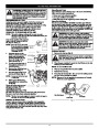
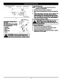
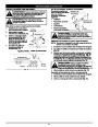
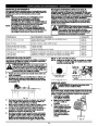
WARNING: Always wear eye, hearing, foot and
body protection to reduce the risk of injury when
operating this unit.
sides.
NOTE: Do not rest the Hassle-Free™ Cutting Head on the
ground while the unit is running.
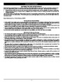
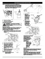
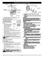
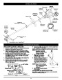
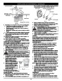
HOLDING THE TRIMMER
Before operating the unit, stand in the operating position (Fig.
0). Check for the following:
The operator is wearing eye protection and proper clothing
With a slightly-bent right arm, the operator’s right hand is
holding the shaft grip
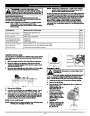
Some line breakage will occur from:
• Entanglement with foreign matter
• Normal line fatigue
• Attempting to cut thick, stalky weeds
•
1
•
•
Forcing the line into objects such as walls or fence posts
•
The operator’s left arm is straight, the left hand holding the
assist handle
The unit is at waist level
The cutting attachment is parallel to the ground and easily
contacts the grass without the need to bend over
TIPS FOR BEST TRIMMING RESULTS
•
•
•
For best trimming results, operate unit at full throttle.
Keep the cutting attachment parallel to the ground.
Do not force the cutting attachment. Allow the tip of the line
to do the cutting, especially along walls. Cutting with more
than the tip will reduce cutting efficiency and may overload
the engine.
•
•
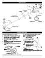
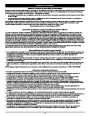
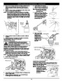
LINE REPLACEMENT
for Hassle-Free™ Cutting Head
Always use Craftsman Hassle-Free™
XTRA QUIET Spiral Line. Choose the
line size best suited for the job at
hand. Red colored line is designed for
cutting grass and small weeds. Black
colored line is designed for cutting
larger weeds and light brush.
• Cut grass over 8 inches (200 mm) by working from top to
bottom in small increments to avoid premature line wear or
engine drag.
•
Cutting from right to left improves the unit's cutting
efficiency. Clippings are thrown away from the operator.
•
Slowly move the trimmer into and out of the cutting area at
the desired height. Move either in a forward-backward or
side-to-side motion. Cutting shorter lengths produces the
best results.
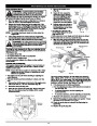
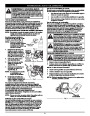
NOTE: Before inserting new line
into the holes in the cutting
head, identify the proper
holes. Follow directions as
shown on the line glide
plate. Do Not attempt to
remove the cutting head
from the unit when
•
•
Trim only when grass and weeds are dry.
The life of your cutting line is dependent upon proper
adherence of explained trimming techniques, what
vegetation is cut, and where vegetation is cut.
For example, the line will wear faster when trimming against a
foundation wall as opposed to
trimming around a tree.
replacing line.
Fig. 10
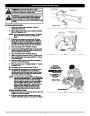
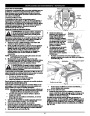
DECORATIVE TRIMMING
Decorative trimming is
accomplished by removing all
vegetation around trees, posts,
fences and more.
WARNING: Do not remove or alter the line cutting
blade assembly. Excessive line length will make the
clutch overheat. This may lead to serious personal
injury or damage to the unit.
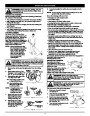
1
.
Remove the old line and line glide plate from the cutting
head.
Rotate the whole unit so that the
cutting attachment is at a 30°
Cutting
Head
Line Glide
Plate
Fig. 14
angle to the ground (Fig. 14).
2.
3.
Clean entire surface of cut-
ting head. Note positions “A”
and “B” on the cutting head.
Arrow
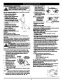
USING THE TWIST AND EDGE™ FEATURE
WARNING: Before you begin using any
attachment, read and understand the manual that
came with the attachment. Follow all safety
information contained within.
Reinstall line glide plate (Fig.
11).
Align arrow with:
“A” when using medium (red)
or large (black) line, or
Fig. 11
WARNING: To avoid serious personal injury and
damage to the unit, shut the unit off before
removing or installing add-ons.
“B” when using lines with
diameters smaller than
medium (red) line
NOTE: Line glide plate must
be reinstalled in
cutting head before
inserting new line.
Positioning
You can convert this unit to edge grass.
Tunnel
1.
2.
3.
Make sure the unit is turned
90˚ Edging Hole
(Trimmer Only)
completely off.
Turn the knob counterclockwise
to loosen coupler (Fig. 15).
4.
5.
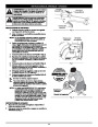
Insert both ends of your
line through the proper
holes in the side of the
cutting head (Fig. 12).
Coupler
Push in the release button (Fig.
16) and twist the shaft 90° until
the release button snaps into the
90° hole (Fig. 15).
Fig. 12
Pull the line and make
sure the line is against the
hub and is fully extended
through the positioning
tunnels (Fig. 13).
Line against
the hub
4.
Turn the knob clockwise to lock
the coupler (Fig. 17).
Knob
Positioning
Tunnel
Fig. 15
Fig. 13
8
| Categories | Craftsman Lawn Mower Manuals, Lawn Mower Manual |
|---|---|
| Tags | Craftsman 316 796170 |
| Download File |
|
| Document Type | Operator's Manual |
| Language | English |
| Product Brand | Craftsman. Customer Service Representatives are available by phone: Canada 1-888-225-4886 USA 1-888-384-9939, Lawn Mower |
| Document File Type | |
| Publisher | craftsman.com |
| Wikipedia's Page | Craftsman (tools) |
| Copyright | Attribution Non-commercial |
(0 votes, average: 0 out of 5)