


6
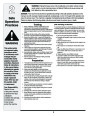
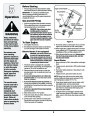
WARNING: NEVER attempt to make
any adjustments while the engine is
running, except where specified in the
operator’s manual.
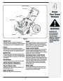
Shave Plate
1.
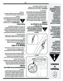
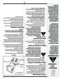
To check the adjustment of the shave plate, place the
unit on a level surface. The wheels, shave plate and
augers should all contact level surface. Note that if the
shave plate is adjusted too high, snow may blow under
the housing. If the shave plate wears out excessively,
or the unit does not self-propel, the shave plate may
be too low and needs to be adjusted.
Adjustments
&
NOTE: On new units or units with a new shave plate
installed, the augers may be slightly off the ground.
Maintenance
2.
To adjust, tip the snow thrower back so that it rests on
the handle. Loosen the four lock nuts and bolts which
secure the shave plate to the housing. See Figure 7.
Move the shave plate to desired position and retighten
the nuts and bolts securely.
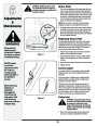
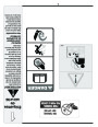
3IDE�6IEW
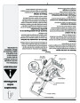
Replacing Shave Plate
The shave plate is attached to the bottom of the auger
housing and is subject to wear. It should be checked
periodically. There are two wearing edges and the shave
plate can be reversed. Refer to Figure 7. To replace or
reverse the shave plate proceed as follows:
WARNING
Disconnect the
spark plug wire
1.
Remove the carriage bolts and hex lock nuts which
and ground it against
the engine to prevent
unintended starting.
attach it to the snow thrower housing.
Figure 7
2.
Install new shave plate (or reverse), making sure the
heads of the carriage bolts are on the inside of the
housing.
Adjust the shave plate according to instructions above
Tighten securely.
3.
4.
NEVER attempt
to make any
adjustments while
the engine is
running, except
where specified in
the operator’s
manual.
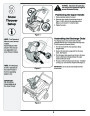
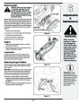
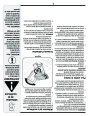
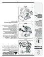
Control Cable
As a result of both the control cable and the drive belt
stretching due to wear, periodic adjustments may be
necessary.
If the auger seems to hesitate when rotating while the
engine maintains a constant speed, an adjustment is
necessary. Proceed as follows:
The upper hole in the control handle provides for an
adjustment in cable tension. To adjust, disconnect the
end of control cable from the bottom hole in the control
handle and reinsert it in the upper hole. Insert the cable
from the outside as shown in Figure 8. Test the snow
thrower to see if there is a noticeable difference.
Before servicing,
repairing, or
inspecting,
disengage the
control bail and
stop engine. Wait
until all moving
parts have come to a
complete stop.
Carburetor
Figure 8
WARNING: If any adjustments need to
be made to the engine while the engine
is running (e.g. carburetor), keep
clear of all moving parts. Be careful of
muffler, engine and other surrounding
heated surfaces.
1.
Refer to the separate engine manual, packed with
your unit, for carburetor adjustment information.
10
| Categories | MTD Snow Blower Manuals, Snow Blower Manuals |
|---|---|
| Download File |
|
| Document Type | Owner's Manual |
| Language | English |
| Product Brand | MTD, Snow Blower |
| Document File Type | |
| Publisher | mtdproducts.com |
| Wikipedia's Page | MTD Products |
| Copyright | Attribution Non-commercial |
(0 votes, average: 0 out of 5)