


en
As Required
3. The auger gear case is lubricated at the
factory and does not require additional
lubrication. If for some reason the lubricant
leaks out, have the auger gear case checked
by a factory authorized service center.
How To Check And Adjust The Cables
The traction drive cable and the auger drive
cable are adjusted at the factory. During normal
use, a cable can become stretched and must be
checked and adjusted as follows.
The following adjustment should be preformed
more than once each season.
1.
Adjust the auger drive belt after the first 2 to
4 hours, again at mid−season, and twice
each season thereafter. See “How To Adjust
The Auger Drive Belt” in the Maintenance
section.
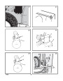
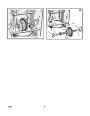
How To Check The Cables (Figure 16)
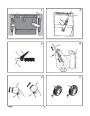
How To Adjust The Height Of The Skids
1.
2.
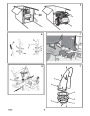
To check for correct adjustment, disconnect
(Figure 1)
the “Z” fitting (1) from the drive lever (2).
Lubrication
Move the drive lever (2) forward until the
drive lever (2) is contacting the plastic
bumper (3).
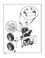
This snow thrower is equipped with two height
adjustable skids (7). These skids elevate the
front of the snow thrower. For normal hard
surfaces, such as a paved driveway or walk,
adjust the skids as follows.
Every 10 Hours (Figure 14)
1.
2.
3.
Lubricate the Zerk fittings (1) every ten
3. The control cable is correctly adjusted if the
center of the “Z” fitting (1) is aligned (4)
with the hole in the drive lever (2) and there
in no droop in the cable.
hours with a grease gun.
Each time a shear bolt is replaced, the auger
shaft must also be greased.
Lubricate all pivot points.
1. Put the snow thrower on a level surface.
2.
Make sure both tires are equally inflated. The
correct air pressure is 14 PSI (1 BAR) to 17
PSI (1.25 BAR). Do not exceed the
maximum amount of air pressure shown on
the side of the tire.
How To Adjust The Auger Drive Cable
Every 25 Hours
1.
Remove the gas from the gas tank. Stand
the snow thrower up on the front end of the
auger housing.
Chute Rotation Gear
3.
4.
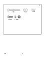
Put the extra shear bolts (found in the parts
bag) under each end of the scraper bar (15)
next to the adjustable skids (7).
Loosen the mounting nuts (16) that hold the
adjustable skids (7). To bring the front of the
snow thrower down, raise each adjustable
skids (7). Tighten the mounting nuts (16).
(Figure 5) Lubricate the chute rotation gear (1)
with automotive type oil.
WARNING: Drain the gasoline
outdoors, away from fire or flame.
2.
3.
(Figure 16) Disconnect the “Z” fitting (1)
from the drive lever (2).
(Figure 17) Pull the spring cover up to
expose the spring (5). Push the cable (6)
through the spring (5) to expose the square
end (7) on the cable (6).
Chains
1.
(Figure 1) Move the speed shift lever (6) to
first gear.
Remove the gas from the gas tank. Stand
the snow thrower up on the front end of the
auger housing (4).
WARNING: Drain the gasoline
outdoors, away from fire or flame.
NOTE: For rocky or uneven surfaces, raise
the front of the snow thrower by moving the
adjustable skids (7) down.
2.
4.
Hold the square end (7) with pliers and
adjust the locknut (8) in or out until the
excess slack is removed.
WARNING: Be certain to maintain
proper ground clearance for the
area to be cleared. Objects such as
gravel, rocks or other debris, if struck by
the impeller, can be thrown with sufficient
force to cause personal injury, property
damage or damage to the snow thrower.
5. Pull the cable (6) back through the spring
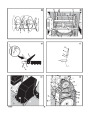
3.
(Figure 23) Loosen the bolts (3) on each
side of the bottom panel (2).
Remove the bottom panel (2).
(Figure 15) Lubricate the chains (5) with a
chain type lubricant.
Wipe the hexshaft and sprockets (6) with
5W30 motor oil.
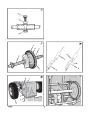
NOTE: If grease or oil come in contact
with the disc drive plate (1) or the friction
wheel (3), damage can result. Clean off
any oil or grease with a alcohol base
solvent.
(5).
(Figure 16) Connect the “Z” fitting (1) to the
drive lever (2).
6.
4.
5.
NOTE: When the auger drive belt is adjusted
or replaced, check and adjust the cable.
6.
How To Adjust The Traction Drive Cable
How To Adjust The Scraper Bar
1.
Remove the gas from the gas tank. Stand
the snow thrower up on the front end of the
auger housing.
(Figure 1)
After considerable use, the scraper bar (15) will
become worn. The scraper bar (15), in
conjunction with the skids, must be adjusted to
allow 1/8 inch clearance between the scraper
bar (15) and the sidewalk or area to be cleared.
WARNING: Drain the gasoline
outdoors, away from fire or flame.
7.
8.
(Figure 23) Install the bottom panel (2).
Tighten the bolts (3) on each side of the
bottom panel (2).
2.
(Figure 23) Loosen the bolts (3) on each
side of the bottom panel (2).
1.
Put the snow thrower on a level surface.
Items Not To Lubricate (Figure 15)
3.
4.
Remove the bottom panel (2).
(Figure 16) Disconnect the “Z” fitting (1)
from the traction drive lever (2).
1.
Do not lubricate the hex shaft and
sprockets (6). All bearings and bushings are
lifetime lubricated. For storage, put a slight
amount of 5W−30 motor oil on a cloth and
wipe the hex shaft and sprockets (6) to
prevent rust.
2. Make sure both tires are equally inflated. The
correct air pressure is 14 PSI (1 BAR) to 17
PSI (1.25 BAR). Do not exceed the
maximum amount of air pressure shown on
the side of the tire.
5.
6.
(Figure 28) Slide the cable boot (3) off the
cable adjustment bracket (4).
Push the bottom of the traction control
cable (5) through the cable adjustment
bracket (4) until the “Z” hook (6) can be
removed.
3.
4.
5.
Loosen the carriage bolts and nuts that
hold the scraper bar (15) to the auger
housing (4).
Adjust the scraper bar (15) to allow 1/8 inch
clearance between the scraper bar (15) and
the sidewalk or area to be cleared.
2.
If grease or oil comes in contact with the
disc drive plate (1) or the friction wheel
(3)
, the friction wheel (3) can be damaged.
7.
Remove the “Z” hook (6) from the cable
Make sure to thoroughly clean the disc drive
plate (1) and the friction wheel (3).
adjustment bracket (4). Move the “Z” hook
(6)
down to the next adjustment hole.
CAUTION: Any greasing or oiling of the
above components can cause
contamination of the friction wheel (3). If
the disc drive plate (1) or the friction
wheel (3) become contaminated with
grease or oil, damage to the friction wheel
will result.
Tighten the carriage bolts and nuts. Make
sure that the scraper bar (15) is parallel with
the sidewalk or area to be cleared.
8. Pull the traction control cable (5) up
through the cable adjustment bracket (4).
9. Put the cable boot (3) over the cable
adjustment bracket (4).
10.(Figure 16) Install the “Z” fitting (1) to the
traction drive lever (2).
6. To extended the life of the scraper bar (15),
remove and reverse the mounting of the
scraper bar (15).
1
742237
12
| Categories | Murray Snow Blower Manuals, Snow Blower Manuals |
|---|---|
| Tags | Murray 1695539 |
| Download File |
|
| Document File Type | |
| Copyright | Attribution Non-commercial |
(1 votes, average: 5 out of 5)
Lawn and Garden readers have rated Murray Walk Behind 1695539 8.0 24-Inch Dual Stage Snow Blower Owners Manual 5.0 out of 5.0 based on 1 product reviews. very good snowblover