


en
6.
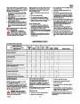
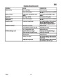
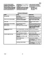
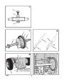
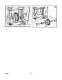
(Figure 25) Note the position of the friction
wheel (4). The correct distance “A” from the
right side of the friction wheel (4) to the
outside of the motorbox is as follows:
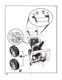
13.(Figure 32) Install the hex shaft (8) and
bearings (7) with the four bolts removed
earlier.
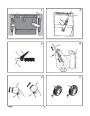
1. Drain the fuel tank.
2.
3.
Let the engine run until it is out of gasoline.
Never store the snow thrower with fuel in the
tank inside a building where ignition sources
are present such as hot water and space
heaters, clothes dryers, and the like. Allow the
engine (motor) to cool before storing in any
enclosure.
Make sure the washers (17) are properly
installed in the original position. Also,
make sure the two washers (13) are
properly aligned with the actuator arms
(14).
Tire Size
Distance “A”
12
16
and 13 inch
4-1/8” (10.5 cm)
4-5/16” (10.95 cm)
inch
If the friction wheel (4) is not in the correct
position, adjust as follows.
14.
15.
Make sure the hex shaft (8) turns freely.
4.
5.
Drain the oil from the warm engine. Fill the
(Figure 30) Install the right wheel, axle (11),
and drive sprocket (12) with the fasteners
removed earlier. Install the chain (15) onto
the drive sprocket (12).
engine crankcase with new oil.
How To Adjust The Friction Wheel
Thoroughly clean the snow thrower.
1.
2.
3.
4.
(Figure 1) Position the shift speed lever (6)
in the lowest forward speed.
(Figure 9) Loosen the bolts (1) on the
speed control rod (8).
(Figure 25) Move the friction wheel (4) to
the correct position.
6. Lubricate all lubrication points. See the
Maintenance section.
16.
17.
Check the adjustment of the friction wheel.
See “How To Adjust The Friction Wheel” in
this section.
Make sure the friction wheel and the disc
drive plate are free from grease or oil.
7.
Be sure that all nuts, bolts and screws are
securely fastened. Inspect all visible moving
parts for damage, breakage and wear.
Replace if necessary.
(Figure 9) Tighten the bolts (1) on the
8. Cover the bare metal parts of the blower
housing, auger, and the impeller with spray
rust preventative lubricant.
9. Put the unit in a building that has good
ventilation. Store in a clean and dry area, but
NOT near a stove, furnace or water heater
which uses a pilot light or any device that can
create a spark.
18.
19.
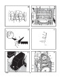
(Figure 23) Install the bottom panel (2).
speed control rod (8).
Tighten the bolts (3) on each side of the
5.
6.
(Figure 23) Install the bottom panel (2).
bottom panel (2).
Tighten the bolts (3) on each side of the
20.
21.
Install the left wheel (10) to the axle (11)
bottom panel (2).
with the fasteners removed earlier.
Connect the spark plug wire.
How To Replace The Friction Wheel
If the friction wheel is worn or damaged, the
snow thrower will not move forward. The friction
wheel must be replaced as follows.
How To Replace the Auger Shear Bolt
10.
If the machine must be stored outdoors,
block up the snow thrower to be sure the
entire machine is off the ground.
The augers are secured to the auger shaft with
special shear bolts. These shear bolts are
designed to break and protect the machine if an
object becomes lodged in the auger housing. Do
not use a harder bolt as the protection provided
by the shear bolt will be lost.
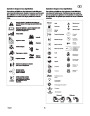
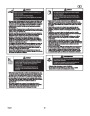
WARNING: For safety and to
protect the machine, use only
original equipment shear bolts.
1.
(Figure 1) Remove the gas from the gas
tank. Stand the snow thrower up on the front
end of the auger housing (4).
WARNING: Drain the gasoline
outdoors, away from fire or flame.
11.
Cover the snow thrower with a suitable
protective cover that does not retain
moisture. Do not use plastic.
How To Order Replacement Parts
The replacement parts are shown either on the
back pages of this Instruction Book or in a
separate Parts List Book.
Use only manufacturer’s authorized or approved
replacement parts. Do not use attachments or
accessories not specifically recommended for
this unit. In order to obtain proper replacement
parts you must supply the model number (see
nameplate).
2.
3.
Disconnect the spark plug wire.
(Figure 29) Remove the fasteners that
secure the left wheel (10). Remove the left
wheel (10) from the axle (11).
To replace a broken shear bolt, proceed as
follows. Extra shear bolts were provided in the
assembly parts bag.
4.
Loosen the bolts (3) on each side of the
1.
2.
3.
4.
(Figure 1) Move the stop switch (13) to the
bottom panel (2).
stop position. Disengage all controls.
5.
6.
Remove the bottom panel (2).
Disconnect the spark plug wire. Make sure
all moving parts have stopped.
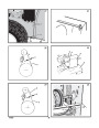
(Figure 14) Lubricate the auger shaft Zerk
fitting (1), if equipped, with a grease gun.
(Figure 30) Remove the fasteners that
secure the drive sprocket (12) to the axle
(11).
To obtain replacement parts, contact your local
Dealer.
7.
8.
Remove the right wheel, axle (11), and drive
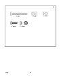
(Figure 26) Align the hole in the auger with
the hole in the auger shaft. Install the new
shear bolt (2), spacer (3), and locknut (4).
sprocket (12).
Replacement parts for the engine, transaxle, or
transmission, are available from the
manufacturer’s authorized service centre found
in the yellow pages of the telephone directory.
Also, see the individual engine or transmission
warranties to order replacement parts.
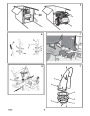
(Figure 31) Remove the four bolts (16) that
hold the bearings (7) on each side of the
hex shaft (8).
5.
Connect the spark plug wire.
9.
(Figure 32) Remove the hex shaft (8) and
How To Prepare The Snow Thrower For
Storage
bearings (7).
NOTE: Take special note of the position of
When ordering the following information is
required:
the washers (17).
WARNING: Do not remove gasoline
while inside a building, near a fire,
or while you smoke. Gasoline
10.
11.
12.
(Figure 27) Remove the three fasteners (4)
(1)
(2)
(3)
(4)
The Model Number
Serial Number
Part Number
Quantity
that hold the friction wheel (5) to the hub
(6).
fumes can cause an explosion or a fire.
(Figure 27) Remove the friction wheel (5)
from the hub (6). Slip the friction wheel (5)
off the hex shaft (8).
If the snow thrower is to be stored for an
extended period, refer to the engine
manufacturer’s operating manual (included with
some models) for important maintenance or
storage details.
Assemble the new friction wheel (5) onto
hub (6) with the fasteners removed earlier.
1
742237
14
| Categories | Murray Snow Blower Manuals, Snow Blower Manuals |
|---|---|
| Tags | Murray 1695539 |
| Download File |
|
| Document File Type | |
| Copyright | Attribution Non-commercial |
(1 votes, average: 5 out of 5)
Lawn and Garden readers have rated Murray Walk Behind 1695539 8.0 24-Inch Dual Stage Snow Blower Owners Manual 5.0 out of 5.0 based on 1 product reviews. very good snowblover