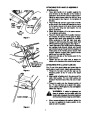
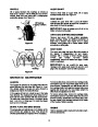


TRACTION DRIVE/AUGER CLUTCH LOCK
SECTION 7: OPERATION
(See Figure 14)
The traction drive clutch is located on the right handle.
Squeeze the traction drive clutch to engage the wheel
drive. Release to stop.
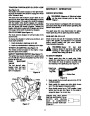
BEFORE STARTING
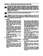
WARNING: Observe all Warning Labels
on the snow thrower prior to use. See
Figure 1.
This same lever also locks the auger clutch so you
can turn the chute crank without interrupting the snow
throwing process. If the auger drive clutch is engaged
with the traction drive clutch engaged, the operator
can release the auger drive clutch (on the left handle)
and the augers will remain engaged. Release the
traction drive clutch to stop both the augers and wheel
drive (auger drive clutch must also be released).
Your snow thrower is shipped with oil; however,
you must check the oil level before operating. Be
careful not to overfill.
The spark plug wire was disconnected for safety.
Attach spark plug wire to spark plug before starting.
CHUTE CRANK (See Figure 14)
The chute crank is located on left hand side of the
snow thrower.
GAS AND OIL FILL-UP
To change the direction in which snow is thrown, turn
chute crank as follows:
Check oil level and add oil if necessary. Service the
engine with gasoline as instructed in the separate
engine manual packed with your snow thrower.
Read instructions carefully.
1.
2.
Crank clockwise to discharge to the left.
Crank counterclockwise to discharge to the right.
WARNING: Never
fill
fuel
tank
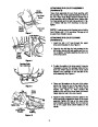
THROTTLE CONTROL (See Figure 17)
The throttle control is located on the engine. It regu-
lates the speed of the engine.
indoors. Never fill fuel tank with engine
running or while engine is hot. Do not
smoke when filling fuel tank.
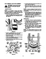
SAFETY IGNITION SWITCH (See Figure 17)
The ignition key must be inserted in the switch before
the unit will start. Remove the ignition key when snow
thrower is not in use.
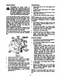
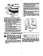
TO START ENGINE
1.
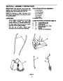
Attach spark plug wire to spark plug. Make
certain the metal loop on end of the spark plug
wire (inside the boot) is fastened securely over
the metal tip on the spark plug. See Figure 18.
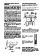
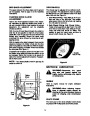
FUEL
SHUT-OFF
VALVE
Closed
The fuel shut-off valve,
located under fuel tank,
controls fuel flow from
tank. (If equipped)
Metal Loop
on Spark
Plug Wire
Open
Figure 16
Rubber Boot
Figure 18
Choke
Primer
2.
3.
4.
Make certain the fuel cutoff valve is in the OPEN
(vertical) position.
Make certain the auger and drive clutch levers
are in the disengaged (released) position.
Move throttle control up to FAST position. Insert
ignition key into slot. See Figure 19. Be certain it
snaps into place. Do not turn key.
ENGINE WILL NOT START
UNLESS IGNITION KEY IS IN-
Rope
Start
Ignition
Key
Throttle
Control
SERTED
SLOT
INTO
CARBURETOR
IGNITION
Handle
IN
COVER. DO NOT TURN IGNI-
TION KEY.
Figure 17
11
| Categories | MTD Snow Blower Manuals, Snow Blower Manuals, Yard Machines Snow Blower Manuals |
|---|---|
| Tags | MTD E600E, MTD E610E, MTD E640F, MTD E660G, MTD Snow Blower Manual, Yard Machines E600E, Yard Machines E610E, Yard Machines E640F, Yard Machines E660G |
| Download File |
|
| Document Type | Owner's Manual |
| Language | English |
| Product Brand | Yard Machines, E600E, E610E, E640F, E660G, Snow Blower |
| Document File Type | |
| Publisher | mtdproducts.com |
| Wikipedia's Page | MTD Products |
| Copyright | Attribution Non-commercial |
(0 votes, average: 0 out of 5)