
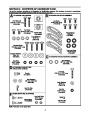
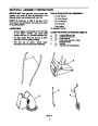
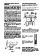
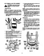


ATTACHING THE HANDLE ASSEMBLY
(Hardware A)
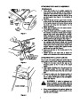
1.
Place right handle (A) in position against the
snow thrower so the flat side of the handle is
against the snow thrower. Secure bottom hole in
handle to snow thrower using hex bolt 3/4" long
and lock washer. See Figure 4. Do not tighten at
this time.
Lock
Washers
2.
Place handle tab over the upper hole in handle
so the curve in the handle tab matches the curve
in the handle. Secure to the snow thrower using
hex bolt 1-3/4" long and lock washer. Do not
tighten at this time.
Cable
Roller
Guide
Hex Bolt
Handle
Tab
3/4”
Long
Hex
Bolt 1-3/4”
Long
3. Attach the left handle (A) in the same manner.
Do not tighten at this time.
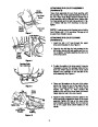
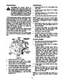
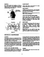
4.
Place the handle panel (B) in position between
the handles. To hold the handle panel in place,
depress both clutch grips against the handles.
While continuing to hold the right hand grip,
release the left hand grip (the auger clutch lock
will keep left hand grip engaged). See Figure 4.
Fasten right side of the handle panel by inserting
two carriage bolts through handle and handle
panel (bolts must go through both the plastic and
metal parts of the handle panel). Secure with
cupped washers (cupped side against handle
panel) and hex nuts. See Figure 5.
Figure 4
5.
Cupped
Washer
Hex
Nut
6.
7.
Secure the left side of the handle panel in the
same manner.
Tighten the four hex bolts used to attach the
bottom of the handles to the snow thrower frame.
NOTE:
Place the CUPPED
side against the
handle panel.
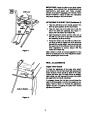
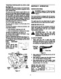
ATTACHING THE CLUTCH CABLES
Carriage
Bolt
The “Z” end of the clutch cables are hooked into the
clutch grips on each handle. Attach cables as follows.
Figure 5
1.
Thread the hex jam nuts all the way up the
threaded portion of the “Z” ends of the clutch
cables.
2.
Make certain all cables are in the grooves of the
cable roller guides. The two roller guides are
located in the lower rear of the unit, one on each
side.
“
Z” End
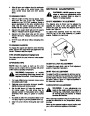
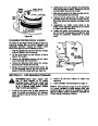
3.
Thread the cable onto the threaded portion of
the “Z” end until there is no slack in the cable,
but the cable is NOT tight. Do not overtighten
cable. See Figure 6.
Hex Jam
Nut
WARNING: If cable is tightened so
there is tension on the cable with the
clutch grip released, the safety features
of the snow thrower may be overridden.
Cable is Straight
4.
When correct adjustment is reached, tighten the
hex jam nut against the bottom portion of the
cable to lock it in position.
Figure 6
7
| Categories | MTD Snow Blower Manuals, Snow Blower Manuals, Yard Machines Snow Blower Manuals |
|---|---|
| Tags | MTD E600E, MTD E610E, MTD E640F, MTD E660G, MTD Snow Blower Manual, Yard Machines E600E, Yard Machines E610E, Yard Machines E640F, Yard Machines E660G |
| Download File |
|
| Document Type | Owner's Manual |
| Language | English |
| Product Brand | Yard Machines, E600E, E610E, E640F, E660G, Snow Blower |
| Document File Type | |
| Publisher | mtdproducts.com |
| Wikipedia's Page | MTD Products |
| Copyright | Attribution Non-commercial |
(0 votes, average: 0 out of 5)