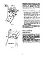
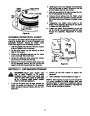


SKID SHOE ADJUSTMENT
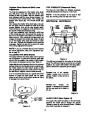
DRIVE WHEELS
The space between the shave plate and the ground
can be adjusted. Refer to page 10 of the Assembly
Instructions.
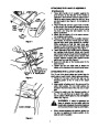
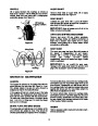
The wheels may be adjusted for two different meth-
ods of operation. The adjustment is made by placing
the klick pins in one of two different holes on the right
side of the unit. See Figure 22.
TRACTION DRIVE CLUTCH
ADJUSTMENT
1.
One Wheel Driving—Place klick pin in the out-
side axle hole on the right side. This position
gives power drive to the left wheel only, making
the unit easier to maneuver.
Refer to the Final Adjustment section of the Assem-
bly Instructions to adjust the traction drive clutch. If
you are uncertain that you have reached the correct
2. Both Wheels Driving—Both Wheels Driving—
Rotate wheel assembly to align hole in hub with
inner hole on axle shaft. Insert klick pin in hole.
Outer axle shaft hole should be visible. This
position is good for heavy snow as there is
power to both wheels. See Figure 22.
adjustment,
the adjustment can be physically
checked as follows.
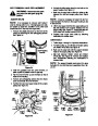
With the snow thrower tipped forward (be certain to
drain the oil and gasoline or drain the oil and place
plastic film under the gas cap if the snow thrower has
already been operated), remove the frame cover
underneath the snow thrower by removing six self-
tapping screws.
Klick Pin in Hub
Holeand Inner AxleHole
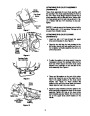
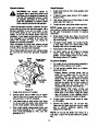
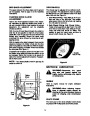
With the traction drive clutch released, there must be
clearance between the friction wheel and the drive
plate in all positions of the shift lever.With the traction
drive clutch engaged, the friction wheel must contact
the drive plate. See Figure 21.
If adjustment is necessary, loosen the hex jam nut on
the traction drive cable and thread the cable in or out
as necessary. Tighten the hex jam nut to secure the
cable when correct adjustment is reached. Reassem-
ble the frame cover.
Outside
Hole in Axle
NOTE: If you placed plastic under the gas cap, be
certain to remove it.
Figure 22
SECTION 9: LUBRICATION
WARNING: Disconnect
the
spark
plug
wire and ground against the
engine before performing any repairs
or maintenance.
Friction
Wheel
ENGINE
Gear Shaft
Refer to engine manual for engine lubrication
instructions.
WARNING: When following instruc-
tions in separate engine manual for
draining oil, be sure to protect frame to
avoid oil dripping onto transmission
parts.
Drive
Plate
CHUTE CRANK
The worm gear on the chute direction crank should
be greased with multipurpose automotive grease.
Figure 21
14
| Categories | MTD Snow Blower Manuals, Snow Blower Manuals, Yard Machines Snow Blower Manuals |
|---|---|
| Tags | MTD E600E, MTD E610E, MTD E640F, MTD E660G, MTD Snow Blower Manual, Yard Machines E600E, Yard Machines E610E, Yard Machines E640F, Yard Machines E660G |
| Download File |
|
| Document Type | Owner's Manual |
| Language | English |
| Product Brand | Yard Machines, E600E, E610E, E640F, E660G, Snow Blower |
| Document File Type | |
| Publisher | mtdproducts.com |
| Wikipedia's Page | MTD Products |
| Copyright | Attribution Non-commercial |
(0 votes, average: 0 out of 5)