


Assembly
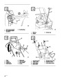
Install Speed Selector Rod
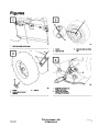
1.
Pull speed selector arm (Fig. 5) to the fully “out”
position and move speed selector (Fig. 7) on
control panel to the R (REVERSE) position to
ease assembly.
Note:
Determine left and right sides of
snowthrower by standing in the normal
operating position.
2.
Install speed selector rod into selector arm, add
one flat washer on the selector rod and secure
with cotter pin (Fig. 5).
Install Handle
1.
Remove tie straps securing control rods to
handle.
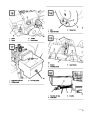
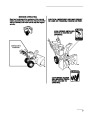
Install Traction Rod
2.
Remove the axle pins from both wheels and
slide the wheels outward on the axle
approximately one inch to make clearance for
assembly of handles.
1.
2.
3.
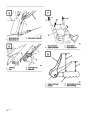
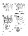
Thread a flange nut (flange side down) onto
traction rod located on left handle (Fig. 6).
Insert traction rod through loop in lower traction
rod (Fig. 6).
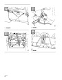
3.
Position left handle against side of unit, align
handle mount holes with holes in side plate, and
secure with two capscrews and curved washers
until finger tight (Fig. 2).
Thread a flange nut (flange side up) onto bottom
of traction control rod below loop in lower
traction rod (Fig. 6).
Note:
Concave side of curved washer goes
against outside of handle.
4.
Adjust the two flange nuts up or down on the
traction control rod until the distance between
the top of the handgrip and the bottom of the
traction control lever#8 (Fig. 7 and 8) is
approximately 4 / inches. This is a
preliminary setting only. Tighten the two
flange nuts finger tight.
Repeat procedure on right side. Make sure
handles are at same height before tightening
handle screws on both sides of unit.
4.
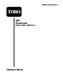
Reinstall the wheels. Note that there are two
holes in each end of the axle. Axle pins are
installed through holes in the wheel hub and
through inner hole of axle (Fig. 3).
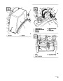
5.
6.
Move speed selector (Fig. 7) into third gear.
Note:
If speed selector will not move into
third gear, an adjustment is necessary:
refer to Adjusting Speed Selector, page
Note:
If snowthrower is to be equipped with
optional tire chains, wheels must be
pinned through outer axle holes.
16.
Make the adjustment before
continuing with assembly.
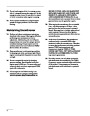
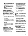
Connect Ignition Wires
Slowly pull machine backward while slowly
depressing traction control lever toward handle.
Adjustment is correct when wheels stop turning
and the distance between the top of the handgrip
and the bottom of the traction control lever is
one to two inches (Fig. 8). Readjust the two
flange nuts, if necessary, to obtain this
dimension and then tighten the two flange nuts
securely.
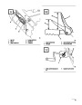
1.
Remove Phillips head screw from engine
bracket, install wire with smaller connector and
reassemble to engine bracket (Fig. 4).
2.
Insert flange head capscrew through large
connector on remaining wire and install in lower
hole in engine bracket (Fig. 4).
8
| Categories | Snow Blower Manuals, Toro Snow Blower |
|---|---|
| Tags | Toro 38052 |
| Model Number | 38052 |
| Model Year | 1995 |
| Download File |
|
| Document Type | Operator's Manual |
| Language | English |
| Serial Number | 59000001 - 59999999 |
| Product Name | 521 Snowthrower |
| Product Brand | Toro. Customer Service Representatives are available by phone:
Monday - Friday 7:30 a.m. to 9:00 p.m. (CDT) - Saturday 8:00 a.m. to 8:00 p.m. (CDT) - Sunday 10:00 a.m. to 8:00 p.m. (CDT)
Canada 1-888-225-4886 USA 1-888-384-9939, Snow Blower |
| Product Type | Snowthrower |
| Product Series | Snowthrower, Two Stage Small Frame |
| Swath | 21 inch |
| Discharge | Two Stage |
| Engine Manufacturer | Tecumseh |
| Engine Motor Model # | HSSK50-67259N |
| Engine Motor Size | 5 hp |
| Engine Motor Type | 4 Cycle |
| Transmission Speed | 3 Forward/1 Reverse |
| Transmission Type | Friction Disc |
| Document File Type | |
| Publisher | toro.com |
| Wikipedia's Page | Toro Company |
| Copyright | Attribution Non-commercial |
(0 votes, average: 0 out of 5)