
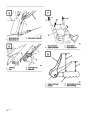
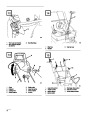
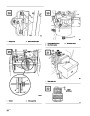


Install Auger Drive Control
Linkage
2.
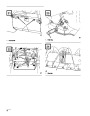
Apply No. 2 general purpose grease to worm
gear. Next, mount worm gear and bracket to
mounting flange and secure with pyramidal
washer and locknut (Fig. 12).
1.
2.
3.
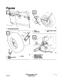
Loosen jam nut above clevis on upper control
rod (Fig. 9).
3.
4.
5.
Slide worm gear into teeth of chute retaining
ring and tighten locknut (Fig. 12).
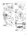
Align holes in clevis and lower control rod and
insert clevis pin (Fig. 9).
Tighten the locknut securing chute control
bracket against left handle (Fig. 11).
Check the distance between the top of the
handgrip and the bottom of the auger control
lever (Figs. 7 & 10). Distance should be
approximately four inches. This is a
preliminary setting only.
Check operation of chute control rod. Move
worm gear slightly outward if binding is evident.
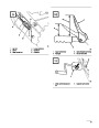
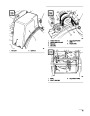
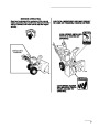
Secure Chute Deflector
4.
Compress auger control lever slowly toward
handgrip. The amount of force to compress the
lever will increase noticeably when slack is
removed from the drive belt (approximately
one-half of lever movement). Adjustment is
correct when the force begins to increase and the
distance between the top of the handgrip and the
bottom of the auger control lever is one to two
inches.
1.
Pivot deflector upward and back until deflector
stop passes over lip on top of chute.
2.
Secure left side of deflector to discharge chute
using parts as illustrated in Figure 13. Make sure
rubber washer and friction plate are positioned
between chute and deflector and friction plate
tabs fit into holes in deflector. See Figure 13 for
proper installation sequence of parts.
Note:
If force does not noticeably increase,
remove the belt cover (refer to
Note:
Concave side of curved washer goes
against large flat washer.
Replacing Auger/ Impeller Drive Belt,
steps 1-2, page 15) and measure the
one to two inch dimension above the
handgrip at the point where the slack is
removed from the auger drive belt.
3.
Tighten nuts on both sides of deflector. Do not
over-tighten nuts so that excessive force is
required to change deflector angle.
5.
6.
To adjust the distance, remove clevis pin, loosen
jam nut and thread clevis up or down to increase
or decrease distance between handgrip and auger
control lever (Fig. 9).
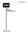
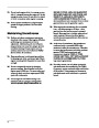
Check Tire Pressure
IMPORTANT: Check pressure of tires
because they are over-inflated at the factory
for shipping. Therefore, before the
snowthrower is operated, reduce pressure in
both tires to 7-15 psi equally.
When adjustment is correct, install clevis pin
and secure it in place with the cotter pin. Tighten
jam nut to secure clevis (Fig. 9).
Install Chute Control Rod
1.
Assemble chute control bracket and rod to left
side of handle with capscrew and locknut. Leave
locknut loose until assembly is completely
mounted (Fig. 11).
9
| Categories | Snow Blower Manuals, Toro Snow Blower |
|---|---|
| Tags | Toro 38052 |
| Model Number | 38052 |
| Model Year | 1995 |
| Download File |
|
| Document Type | Operator's Manual |
| Language | English |
| Serial Number | 59000001 - 59999999 |
| Product Name | 521 Snowthrower |
| Product Brand | Toro. Customer Service Representatives are available by phone:
Monday - Friday 7:30 a.m. to 9:00 p.m. (CDT) - Saturday 8:00 a.m. to 8:00 p.m. (CDT) - Sunday 10:00 a.m. to 8:00 p.m. (CDT)
Canada 1-888-225-4886 USA 1-888-384-9939, Snow Blower |
| Product Type | Snowthrower |
| Product Series | Snowthrower, Two Stage Small Frame |
| Swath | 21 inch |
| Discharge | Two Stage |
| Engine Manufacturer | Tecumseh |
| Engine Motor Model # | HSSK50-67259N |
| Engine Motor Size | 5 hp |
| Engine Motor Type | 4 Cycle |
| Transmission Speed | 3 Forward/1 Reverse |
| Transmission Type | Friction Disc |
| Document File Type | |
| Publisher | toro.com |
| Wikipedia's Page | Toro Company |
| Copyright | Attribution Non-commercial |
(0 votes, average: 0 out of 5)