


1.
2.
3.
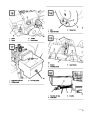
Pull wire off spark plug and make sure wire does
not contact plug accidentally.
3.
4.
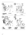
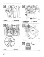
Idle Mixture Screw (Fig. 30)—Close screw by
gently rotating it clockwise until a slight seating
resistance is felt. Next, rotate idle mixture screw
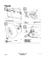
Remove (4) screws securing bottom cover to
frame. Remove cover (Fig. 21).
1–1/2
full turns counterclockwise.
Start engine and let it warm up for
approximately 3 to 5 minutes; then move throttle
to FAST.
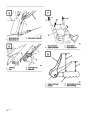
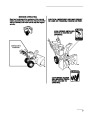
Loosen flange nuts securing selector plate to
control panel. This allows selector plate to move
freely for adjustment (Fig. 28).
4.
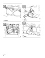
Shift speed selector to third gear and push down
on speed selector plate to move drive assembly!8
to the right. Drive assembly should be / ” from
roll!/8”pin;dimensionif not, slideis correctselector(Fig.plate29).(Fig. 28) until
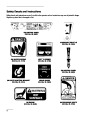
POTENTIAL HAZARD
• Engine must be running so final adjustment of
the carburetor can be performed.
5.
6.
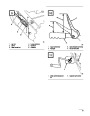
With drive assembly!/8” from contacting roll
pin, tighten flange nuts securing speed selector
plate.
WHAT CAN HAPPEN
Personal injury is possible.
•
HOW TO AVOID THE HAZARD
•
•
Move auger drive and traction drive controls to
DISENGAGE.
Remember to keep hands, feet, face, and other
parts of your body or clothing away from
muffler, auger, discharge chute, and any
moving part(s).
Shift speed selector to R (REVERSE) and back
torollthirdpin toandcheckdriveadjustment.assembly isIfmorespacethanbetween#/16 of
an inch (4.8 mm), repeat steps 2–4.
7.
Reassemble bottom cover with (4) screws.
Adjusting Carburetor
The carburetor has been adjusted at the factory, but an
occasional adjustment may be required.
POTENTIAL HAZARD
• Engine exhaust contains carbon monoxide.
WHAT CAN HAPPEN
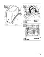
1.
Remove carburetor heater box: see To Start
Engine, paragraph one, steps A & B, page 11.
•
Carbon monoxide is an odorless, deadly
poison.
Note: Skip steps 2 and 3 if the engine will start and
run.
HOW TO AVOID THE HAZARD
•
Do not run engine indoors or in an enclosed
area.
2.
Power Adjusting Screw (Fig. 30)—Close screw
by gently rotating it clockwise until a slight
seating resistance is felt. Next, rotate power
adjusting screw_ one full
5.
Rotate power adjusting screw (Fig. 30)
clockwise—in—1/8 turn at a time until engine
misses because of a lean gasoline mixture. Then
rotate screw counterclockwise—out—1/8 turn at
time until engine runs unevenly because of a rich
gasoline mixture. Next, rotate power adjusting
screw clockwise, back to the midpoint between
the rich and lean settings, so engine runs
smoothly.
turn—360 —counterclockwise.
IMPORTANT: Do not close power adjusting
screw or idle mixture screw too tight because
the screw and seat will likely be damaged.
17
| Categories | Snow Blower Manuals, Toro Snow Blower |
|---|---|
| Tags | Toro 38052 |
| Model Number | 38052 |
| Model Year | 1995 |
| Download File |
|
| Document Type | Operator's Manual |
| Language | English |
| Serial Number | 59000001 - 59999999 |
| Product Name | 521 Snowthrower |
| Product Brand | Toro. Customer Service Representatives are available by phone:
Monday - Friday 7:30 a.m. to 9:00 p.m. (CDT) - Saturday 8:00 a.m. to 8:00 p.m. (CDT) - Sunday 10:00 a.m. to 8:00 p.m. (CDT)
Canada 1-888-225-4886 USA 1-888-384-9939, Snow Blower |
| Product Type | Snowthrower |
| Product Series | Snowthrower, Two Stage Small Frame |
| Swath | 21 inch |
| Discharge | Two Stage |
| Engine Manufacturer | Tecumseh |
| Engine Motor Model # | HSSK50-67259N |
| Engine Motor Size | 5 hp |
| Engine Motor Type | 4 Cycle |
| Transmission Speed | 3 Forward/1 Reverse |
| Transmission Type | Friction Disc |
| Document File Type | |
| Publisher | toro.com |
| Wikipedia's Page | Toro Company |
| Copyright | Attribution Non-commercial |
(0 votes, average: 0 out of 5)