


Install new attachment drive belt:
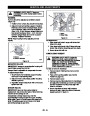
FRICTION DISC REPLACEMENT
1.
Place new attachment belt onto attachment
pulley.
1.
2.
3.
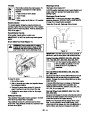
Place unit into service position.
Remove bottom cover by removing six hex bolts.
NOTE: Holding down the attachment clutch lever will
make it easier to reconnect the housing and frame.
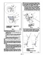
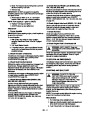
With axle locked, hold one wheel so friction disc
will not rotate and remove three cap screws
holding friction disc to carrier.
2.
Tip housing and frame back together and secure
with hex bolts.
4.
5.
6.
Remove both wheels.
3.
4.
Place belt onto engine sheave.
Remove right and left bearing flanges from frame.
Reposition and secure belt fingers.
Slide hex shaft to the left enough to remove
pinion sprocket from hex shaft.
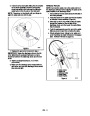
IMPORTANT: With clutch lever engaged, belt finger on
the side opposite the belt idler should be less than
7.
8.
Slide hex shaft to the right enough to remove
friction disc.
1/8
in. (3 mm) from belt, but not touching the belt.
Adjust belt finger as necessary.
Slide new friction disc onto hex shaft.
5.
Check adjustment. See Attachment Clutch/Brake
Adjustment on page 26.
9. Install pinion sprocket and chain on hex shaft,
then replace bearing flanges.
WARNING: AUGER / IMPELLER MUST
STOP within 5 seconds when attachment
clutch lever is released or unit damage or
serious injury may result.
10. Hold wheel so friction disc will not rotate and
secure new friction disc to carrier with three hex
screws removed in step 3.
11.
12.
Replace wheels.
6.
7.
Reconnect chute crank and secure with spring
clip. Reconnect chute lock cable and deflector
cable.
Replace bottom cover.
13. Adjust traction drive clutch (see Traction Drive
Clutch Adjustment on page 28).
Replace belt cover.
TRACTION DRIVE BELT REPLACEMENT
3
1
NOTE: Replacement will be easier with housing and
frame tipped apart and bottom cover off.
1
2
4
1
5
1.
2.
Remove attachment drive belt (see Attachment
Clutch/Brake Adjustment on page 26).
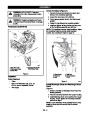
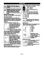
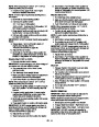
To gain belt clearance, back out the stop bolt from
the frame until the drive plate assembly can
swing past it (Figure 37).
3.
Pull idler away from traction drive belt and
remove belt from idler pulley, engine sheave and
driven pulley (it may be necessary to turn engine
pulley using recoil handle).
4.
5.
Install new traction drive belt onto attachment
pulley and engine sheaves.
8
Pull the drive plate assembly toward the friction
disc and tighten the stop bolt.
1
6
7
NOTE: Make sure the drive plate assembly return
spring remains connected to the frame.
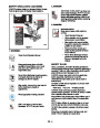
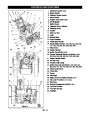
1.
2.
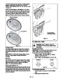
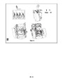
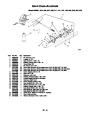
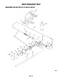
3.Friction Disc
4.Pinion Sprocket
Cap Screw
Hex Screw
5.Bearing Cap
6.Idler Hex Shaft
7.Drive Plate Assembly
8.Stop Bolt
6.
Replace attachment drive belt (see Attachment
Drive Belt Replacement on page 29).
Figure 37
OS7225
GB - 30
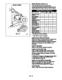
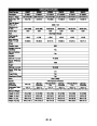
| Categories | Ariens Snow Blower Manuals, Snow Blower Manuals |
|---|---|
| Tags | Ariens 926001, Ariens 926002, Ariens 926003, Ariens 926004, Ariens 926005, Ariens 926006, Ariens 926007, Ariens 926008, Ariens 926009, Ariens 926010, Ariens 926011, Ariens 926012, Ariens 926101, Ariens 926102, Ariens 926103, Ariens 926300, Ariens 926301, Ariens 926302, Ariens 926303, Ariens 926304, Ariens 926500, Ariens 926501, Ariens 926504 |
| Download File |
|
| Document Type | Service Manual |
| Language | English |
| Product Brand | Ariens, Snow Blower |
| Document File Type | |
| Publisher | ariens.com |
| Wikipedia's Page | Ariens |
| Copyright | Attribution Non-commercial |
(0 votes, average: 0 out of 5)