


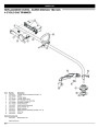
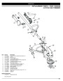

ASSEMBLY INSTRUCTIONS
TB465SS
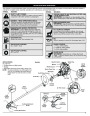
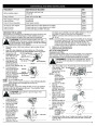
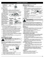
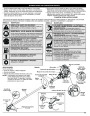
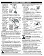
INSTALL CUTTING ATTACHMENT SHIELD
1.
2.
3.
Slide the cutting attachment shield into the shield mount on the
WARNING:
To prevent serious personal injury, never
operate the trimmer without the cutting attachment
shield in place.
cutting attachment.
Align the screw holes Shaft Housing
in the shield with the
Cutting
Attachment
Shield
Shield
Mount
holes in the cutting
attachment (Fig. 4).
Use the following instructions if the cutting attachment shield on
your unit is not installed. Use only the instructions that apply to the
type of shaft and shield that your unit is equipped with.
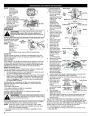
Place a hex lock nut
Cutting
into one of the three Attachment
recessed holes on
TB415CS
1.
Cutting Attachment
Shield
Shaft
Housing
Fig. 4
the top of the
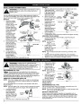
Place the cutting
attachment shield
onto the shaft
cutting attachment
Nuts (3)
Recessed
Holes
shield (Fig 5).
Install a screw into the
hole from the bottom
of the cutting
attachment shield and
screw it into the nut
installed in step 2 (Fig.
5). Do not tighten.
housing. Be sure the
guard mounting
bracket slides into
the slot on the edge
of the cutting shield.
Rotate the shield
into place,
counterclockwise.
The holes in the
guard mounting
bracket and cutting
attachment shield
will line up (Fig. 1).
From inside the cutting
attachment shield,
push the square bolt
through the hole until
the threaded end
protrudes through the
guard mounting
bracket (Fig. 2).
Guard
Mounting
Bracket
Hex Lock
Nut
Screws (3)
Fig. 1
Guard Mounting
Bracket
Washer
Fig. 5
4.
Repeat steps 2 and
3 until all three screws have been started, then tighten securely.
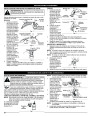
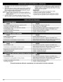
ADJUSTING THE D-HANDLE
1.
Locate the wing nut on the D-Handle. Loosen the wing nut
enough to loosen the
D-Handle (Fig. 6).
Wing Nut
Square Bolt
2.
3.
NOTE: Do not remove
wing nut,
washer, or bolt.
Rotate the D-Handle
to the upright
Fig. 2
Square Bolt
2.
position on the front
side of the shaft
housing (Fig. 6).
Fig. 6
Put the washer on
the bolt, then screw
the wing nut onto the
bolt and tighten.
NOTE: The D-handle should slant towards the powerhead of the
unit.
Hold the unit in the operating position (Fig. 15). If necessary,
reposition the D-handle to the location that provides the best grip.
3.
4.
Fig. 3
Figure 3 shows the
Tighten the wing nut until the D-Handle is secure.
installation process from underneath the unit.
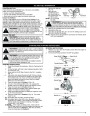
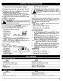
OIL AND FUEL INFORMATION
3.
Remove the oil plug
/ dipstick from the
WARNING:
OVERFILLING OIL CRANKCASE MAY
CAUSE SERIOUS PERSONAL INJURY. Check and maintain
the proper oil level in the crank case; it is important and
cannot be overemphasized. Check the oil before each use
and change it as needed. See Changing the Oil.
crankcase (Fig. 9).
4.
Pour the entire
bottle of oil into the
Oil Fill
oil fill hole (Fig. 9).
RECOMMENDED OIL TYPE
Using the proper type and weight of oil in the crankcase is
extremely important. Check the oil before each use and change
the oil regularly. Failure to use the correct oil, or using dirty oil, can cause
premature engine wear and failure. Use a high-quality SAE 30 weight oil of
API (American Petroleum Institute) service class SF, SG, SH.
NOTE: Never add oil to
the fuel or fuel
tank.
Fig. 8
O-Ring
5.
Wipe up any oil that
may have spilled
and reinstall the oil
fill plug / dipstick.
Oil Fill
Plug/Dipstick
ADDING OIL TO CRANKCASE: INITIAL USE
Oil Fill Hole
NOTE: This unit is shipped without oil. In order to avoid damage
to the unit, put oil in the crankcase before you attempt to
start the unit.
Your unit is supplied with one 3.04 fluid oz. (90 ml) bottle of SAE 30 SF,
SG, SH oil (Fig. 7).
Check oil before each
use and change as
needed. Refer to
Fig. 9
Changing the Oil.
RECOMMENDED FUEL TYPE
NOTE: Save the bottle of oil. It can be used to measure the correct
amount during future oil changes. See Changing the Oil.
Old fuel is the primary reason for improper unit performance. Be
sure to use fresh, clean, unleaded gasoline.
1.
Unscrew the top of
the bottle of oil and
remove the paper
seal covering the
opening. Replace the
top. Next, cut the tip
off the funnel spout
(Fig. 7).
NOTE: This is a four cycle engine. In order to avoid damage to the
unit, do not mix oil with gasoline.
Definition of Blended Fuels
Funnel
Spout
Today's fuels are often a blend of gasoline and oxygenates such as
ethanol, methanol or MTBE (ether). Alcohol-blended fuel absorbs water.
As little as 1% water in the fuel can make fuel and oil separate or form
acids when stored. Use fresh fuel (less than 60 days old), when using
alcohol-blended fuel.
Fig. 7
2.
Place the unit on a flat level surface (Fig. 8).
4
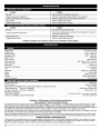
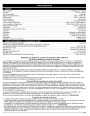
| Categories | Lawn Mower Manual, MTD Lawn Mower Manuals, MTD Trimmer Manuals, Trimmer Manuals, Troy-Bilt Lawn Mower Manuals |
|---|---|
| Tags | MTD TB415CS, MTD TB465SS, Troy Bilt TB465SS, Troy-Bilt TB415CS |
| Download File |
|
| Document Type | Owner's Manual |
| Language | English |
| Product Brand | MTD, Lawn Mower |
| Product Type | Walk Behind Mower |
| Document File Type | |
| Publisher | mtdproducts.com |
| Wikipedia's Page | MTD Products |
| Copyright | Attribution Non-commercial |
(0 votes, average: 0 out of 5)