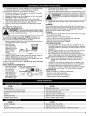


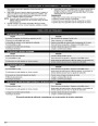
MAINTENANCE AND REPAIR INSTRUCTIONS
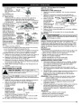
NOTE: It may be
necessary to
• This task should be
performed inside, in a
clean, dust free area.
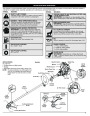
Engine Cover
remove the fuel
cap to reinstall
the air filter
cover.
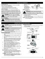
1.
Remove the muffler
cover by pressing
down on it,
Middle Tab
Rear
Slot &
Tab
Front Tab
Front Slot
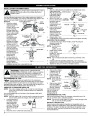
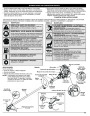
8.
Swing the cover to
separating it from the
engine cover. Using
a flat blade
screwdriver,
disengage the
middle and front
tabs and slots first.
The cover will hinge
off from the rear tab
(Fig. 32).
Fig. 29
the right until the tab
on the air filter cover Air Filter Cover
snaps into place in
Middle Slot
Fig. 32
Top View Of The Engine
Engine Cover
the slot on the back
plate (Fig. 30).
Replace the fuel cap
if it was removed.
Air Filter
9.
Remove Screws
Tab
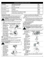
CARBURETOR
ADJUSTMENT
Fig. 30
Muffler
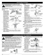
2.
3.
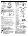
Remove the two (2)
screws on top of the
engine cover with a
Flat-head or T-25
Torx screwdriver
(Fig. 33).
Remove the screw
behind the engine
cover (Fig. 34).
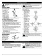
WARNING:
The cutting attachment may spin during
idle speed adjustments. Wear protective clothing and
observe all safety instructions to prevent serious personal
injury.
Fig. 33
The idle speed of the engine is adjustable. An idle adjustment screw
is reached though a hole
Screw
Idle
in the top of the engine
cover (Fig. 31).
Adjustment
Screw
NOTE: Careless
adjustments can
seriously
4.
5.
Disconnect the
spark plug wire.
Fig. 34
Clean dirt from
around the spark
plug. Remove the
spark plug from the
cylinder head by
turning a 5/8 in.
socket
counterclockwise.
Remove the engine
cover (Fig. 33).
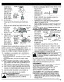
Clean dirt from around
the rocker arm cover.
Remove the screw
holding the rocker arm
cover with a large flat
blade screwdriver or
Torx T-25 bit (Fig. 35).
Remove the rocker
arm cover and gasket.
Pull the starter rope slowly to bring the piston to the top of its
travel, (known as top dead center). Check that:
The piston is at the top of its travel while looking in the spark
plug hole (Fig. 36)
Both rocker arms
move freely, and
both valves are
closed
If these statements
are not true, repeat Intake Clearance:
this step.
Slide the feeler
gauge between the
rocker arm and the
damage your
Rocker Arm Cover
unit. An
Fig. 31
authorized
Spark
Plug
Hole
service dealer should make carburetor adjustments.
Check Fuel
Old fuel is usually the reason for improper unit performance. Drain and
refill the tank with fresh fuel prior to making any adjustments. Refer to Oil
and Fuel Information.
Fig. 35
6.
7.
Clean Air Filter
Rocker Arms Intake
Adjustment
Nuts
The condition of the air filter is important to the operation of the unit.
A dirty air filter will restrict air flow. This is often mistaken for an out
of adjustment carburetor. Check the condition of the air filter before
adjusting the idle speed screw. Refer to Air Filter Maintenance.
Exhaust
Adjust Idle Speed Screw
Feeler Gauge
If, after checking the fuel and cleaning the air filter, the engine still
will not idle, adjust the idle speed screw as follows:
Start the engine and let it run at a high idle for a minute to warm
up. Refer to Starting/Stopping Instructions.
Release the throttle trigger and let the engine idle. If the engine
stops, insert a small phillips or flat blade screwdriver into the
hole in the air filter/muffler cover (Fig. 31). Turn the idle speed
screw in, clockwise, 1/8 of a turn at a time (as needed) until
the engine idles smoothly.
Checking the fuel, cleaning the air filter, and adjusting the idle
speed should solve most engine problems. If not and all of the
following are true:
Fig. 36
1.
2.
8.
•
•
Exhaust
Adjustment Nut
Feeler Gauge
Exhaust
Clearance:
.003-.006 in.
(.076-0.152
mm)
•
•
•
the engine will not idle
Exhaust
Valve Stem
the engine hesitates or stalls on acceleration
there is a loss of engine power
Have the carburetor adjusted by an authorized service dealer.
.003–.006 in.
(.076–0.152 mm)
9.
Intake Valve Stem
Fig. 37
ROCKER ARM CLEARANCE
valve return spring. Measure the clearance between the valve
stem and rocker arm (Fig. 36). Measure both the intake and
exhaust valves.
The recommended clearance for the intake and exhaust is .003 –
in. (.076 – 0.152 mm). Use a standard automotive feeler gauge
WARNING:
To prevent serious personal injury, make
sure the cutting attachment has stopped rotating before
you turn it off and set it down.
.006
This requires disassembly of the engine. If you feel unsure or unqualified
to perform this, take the unit to an authorized service center.
at .005 in. (0.127mm). The feeler gauge should slide between the
rocker arm and valve stem with a slight amount of resistance, without
binding. Figure 37 shows how to measure the clearance.
10. If the clearance is not within specification:
a. Turn the adjusting nut using a 5/16 inch (8 mm) wrench or nut
driver (Fig. 36).
NOTE: Inspect the valve to rocker arm clearance with a feeler
gauge after the first 10 hours of operation and then every
25
hours of operation thereafter.
•
The engine must be cold when checking or adjusting the valve
clearance.
8
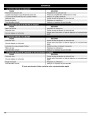
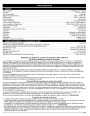
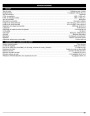
| Categories | Lawn Mower Manual, MTD Lawn Mower Manuals, MTD Trimmer Manuals, Trimmer Manuals, Troy-Bilt Lawn Mower Manuals |
|---|---|
| Tags | MTD TB415CS, MTD TB465SS, Troy Bilt TB465SS, Troy-Bilt TB415CS |
| Download File |
|
| Document Type | Owner's Manual |
| Language | English |
| Product Brand | MTD, Lawn Mower |
| Product Type | Walk Behind Mower |
| Document File Type | |
| Publisher | mtdproducts.com |
| Wikipedia's Page | MTD Products |
| Copyright | Attribution Non-commercial |
(0 votes, average: 0 out of 5)