


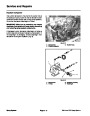

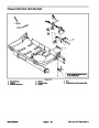


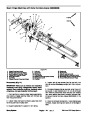


4.
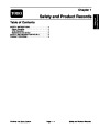
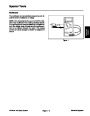
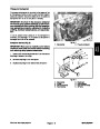
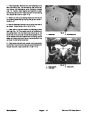
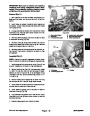
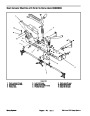
Place diaphragm back disc and new diaphragm onto
each connecting rod. The connecting rods should ex-
tend above the diaphragms when correctly installed
(Fig. 11). Position nylon washer and washer on each
connecting rod and then thread hex bolt into connecting
rod. Torque bolt to 60 ft–lb (81 N–m).
2
1
5.
Make sure that pump casings align and then secure
pump casing assembly by torquing five (5) bolts to 32 ft–
lb (43 N–m).
6.
per cover). Torque bolts to 55 ft–lb (75 N–m).
Secure diaphragm covers to pump using hex bolts (4
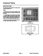
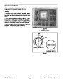
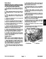
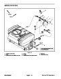
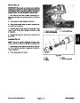
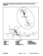
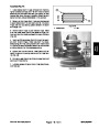
7.
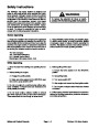
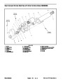
Place new o–rings and valves into diaphragm cover
openings (Fig. 12). Inlet valves should be installed with
the spring down into the cover and should be on the
same side of the pump as the crankshaft grease fitting.
Outlet valves should be installed with the spring up and
away from cover and should be on the same side of the
pump as the crankshaft extension.
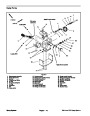
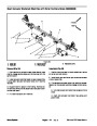
Figure 11
2.
1.
Diaphragm
Connecting rod
1
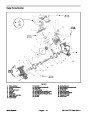
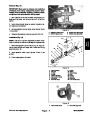
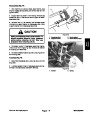
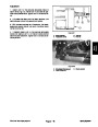
8.
of chamber inlet and outlet. Secure valve chamber with
two (2) hex bolts. Torque bolts 60 ft–lb (81 N–m).
Place valve chamber over valves noting orientation
3
2
2
Figure 12
1.
2.
Inlet (suction)
Inlet valve
3.
Outlet valve
Spray System
Workman 200 Spray System
Page 3 – 14
| Categories | Lawn Mower Manual, Sprinkler and Irrigation Manuals, Toro Sprinkler and Irrigation Manuals |
|---|---|
| Tags | Toro 200 |
| Download File |
|
| Document Type | Service Manual |
| Language | English |
| Product Brand | Toro. Customer Service Representatives are available by phone:
Monday - Friday 7:30 a.m. to 9:00 p.m. (CDT) - Saturday 8:00 a.m. to 8:00 p.m. (CDT) - Sunday 10:00 a.m. to 8:00 p.m. (CDT)
Canada 1-888-225-4886 USA 1-888-384-9939, Lawn Mower |
| Document File Type | |
| Publisher | toro.com |
| Wikipedia's Page | Toro Company |
| Copyright | Attribution Non-commercial |
(0 votes, average: 0 out of 5)