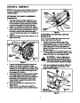
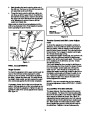
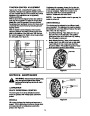
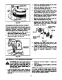


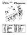

ATTACHING THE CHUTE ASSEMBLY
(Hardware C)
Place chute assembly over chute opening, with the
opening in the chute assembly facing the front of the
unit. Place chute flange keepers beneath lip of chute
assembly, with the flat side down. Secure with hex
bolts and hex lock nuts. Tighten with two adjustable
wrenches. Do not overtighten. See Figure 7.
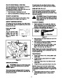
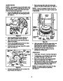
Carriage
Bolts
Hex Lock
Nuts
Lower Chute
Bracket
Hex Bolts
Figure 9
Chute
Assembly
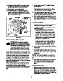
4.
Place one flat washer on the end of the chute
directional control, then insert the end of the con-
trol into the hole in the plastic bushing in the
lower chute bracket. Place another flat washer on
the end of the chute directional control, and insert
hairpin clip into hole in the end of control. See
Figure 10.
Hex Lock
Nut
Chute Flange
Keepers
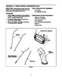
Chute
Directional
Control
Figure 7
Hairpin
Clip
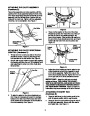
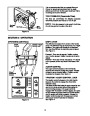
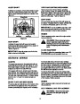
ATTACHING THE CHUTE DIRECTIONAL
CONTROL (Hardware D)
1.
Thread one hex nut onto eye bolt on the chute
directional control. Insert eye bolt through the
hole provided in the left handle. See Figure 8.
Lower Chute
Bracket
2.
Secure with cupped washer (cupped side against
the handle) and other hex nut. Do not tighten until
after attaching the other end of the chute direc-
tional control.
Flat
Washers
Figure 10
5.
Adjust the chute bracket so that the spiral on the
chute directional control fully engages the teeth
on the chute assembly. Tighten the nuts on the
lower chute bracket securely. Tighten the hex nut
on the eye bolt on the chute directional control.
Hex Nut
Cupped
Washer
IMPORTANT: Attach the shift rod and clutch
cables as follows. THEN CHECK THE ADJUST-
MENTS AS INSTRUCTED, AND MAKE ANY FINAL
ADJUSTMENTS NECESSARY BEFORE OPERAT-
ING YOUR SNOW THROWER. Failure to follow the
instructions may cause damage to the snow thrower.
Eye Bolt
ATTACHING THE SHIFT ROD
(Hardware B)
Figure 8
3.
To align the spiral on the chute directional con-
trol, it may be necessary to loosen the carriage
bolts and hex lock nuts which secure the lower
chute bracket to the extension on the left side of
the chute assembly. See Figure 9.
1.
Place the shift lever (on the handle panel) in the
sixth (6) speed position (all the way forward).
2.
Place the bent end of the shift rod into the hole in
the shift arm assembly. Secure with flat washer
and hairpin clip. See Figure 11.
8
| Categories | MTD Snow Blower Manuals, Snow Blower Manuals, Yard Machines Snow Blower Manuals |
|---|---|
| Tags | MTD E600E, MTD E610E, MTD E640F, MTD E660G, MTD E6C0F, MTD Snow Blower Manual, Yard Machines E600E, Yard Machines E610E, Yard Machines E640F, Yard Machines E660G, Yard Machines E6C0F |
| Download File |
|
| Document Type | Owner's Manual |
| Language | English |
| Product Brand | Yard Machines, E600E, E610E, E640F, E660G, E6C0F, Snow Blower |
| Document File Type | |
| Publisher | mtdproducts.com |
| Wikipedia's Page | MTD Products |
| Copyright | Attribution Non-commercial |
(0 votes, average: 0 out of 5)