


3.
4.
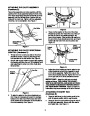
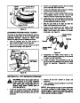
Start threading the ferrule onto the other end of
the shift rod. Push down on the shift rod (and shift
arm assembly) as far as it will go.
Thread the ferrule onto the shift rod until the fer-
rule lines up with the upper hole in the shift lever
(beneath the handle panel). Insert the ferrule into
the upper hole in the shift lever from the left side
when adjustment is correct. Secure with flat
washer and hairpin clip.
Make certain to check for correct adjustment of the
shift rod as instructed in the Final Adjustment section
before operating the snow thrower.
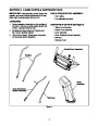
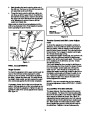
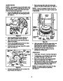
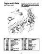
Hex Lock
Nut
Make Sure
Cable is Straight
Hairpin
Clip
Flat
Washer
Figure 12
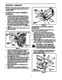
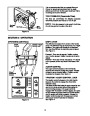
Traction Control and Shift Lever Adjust-
ment
Shift Rod
Ferrule
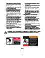
To check the adjustment of the traction control and
shift lever, move the shift lever all the way forward to
sixth (6) position. With the traction control released,
push the snow thrower forward. The unit should move
forward freely. Then engage the traction control grip.
The wheels should stop turning.
Shift Arm
Assembly
Flat
Washer
Now release the traction control grip, and push the unit
again. Move the shift lever back to the fast reverse
position, then all the way forward again. There should
be no resistance in the shift lever, and the wheels
should keep turning.
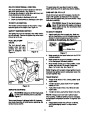
If you have resistance when moving the shift lever or
the wheels stop when they should not, loosen the jam
nut on the traction control cable and unthread the
cable one turn. If the wheels do not stop when you
engage the traction control grip, loosen the jam nut on
the traction control cable and thread the cable in one
turn. Recheck the adjustment and repeat as neces-
sary. Tighten the jam nut to secure the cable when
correct adjustment is reached.
Hairpin
Clip
Figure 11
FINAL ADJUSTMENTS
Auger Control
To check the adjustment of the auger control, push for-
ward on the left hand control (depress the rubber
bumper on end of control). There should be slack in
the cable. Release the clutch grip. The cable should
be straight. Make certain you can depress the auger
drive control grip against the left handle completely.
NOTE: If you are uncertain that you have reached
the correct adjustment, refer to SECTION 7: ADJUST-
MENTS.
If necessary, loosen the hex jam nut and thread the
cable in (for less slack) or out (for more slack) as nec-
essary. Recheck the adjustment. Tighten the jam nut
against the cable when correct adjustment is reached.
See Figure 12.
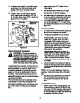
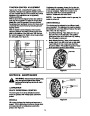
ADJUSTING THE SKID SHOES
The space between the shave plate and the ground
can be adjusted. For close snow removal, place skid
shoes in the low position. Use middle or high position
when area to be cleared is uneven. See Figure 13.
Adjust skid shoes by loosening the four hex nuts and
carriage bolts and moving skid shoes to desired posi-
tion. Make certain the entire bottom surface of skid
shoe is against the ground to avoid uneven wear on
the skid shoes. Retighten nuts and bolts securely.
9
| Categories | MTD Snow Blower Manuals, Snow Blower Manuals, Yard Machines Snow Blower Manuals |
|---|---|
| Tags | MTD E600E, MTD E610E, MTD E640F, MTD E660G, MTD E6C0F, MTD Snow Blower Manual, Yard Machines E600E, Yard Machines E610E, Yard Machines E640F, Yard Machines E660G, Yard Machines E6C0F |
| Download File |
|
| Document Type | Owner's Manual |
| Language | English |
| Product Brand | Yard Machines, E600E, E610E, E640F, E660G, E6C0F, Snow Blower |
| Document File Type | |
| Publisher | mtdproducts.com |
| Wikipedia's Page | MTD Products |
| Copyright | Attribution Non-commercial |
(0 votes, average: 0 out of 5)