


2.
3.
4.
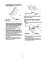
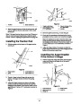
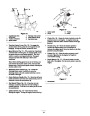
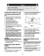
Install the lower link through the outer hole in the lower
control rod as shown in Figure 10.
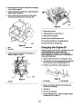
Installing the Chute Control
Rod
Insert the upper control rod through the loop in the
lower link (Fig. 10).
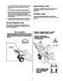
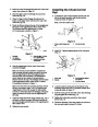
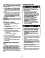
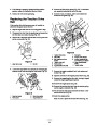
1. Assemble the chute control bracket and rod to the left
side of the handle assembly with the bolt and the
locknut as shown in Figure 12.
Thread a flange locknut (flange side up) onto the
bottom of the upper control rod below the loop in the
lower link (Fig. 10).
Note: Leave the locknut loose.
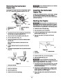
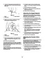
5.
Check the distance between the top of the handgrip and
the bottom of the auger/impeller drive control lever.
The distance should be approximately 4 inches
2
(10.2
centimeters) as shown in Figure 11.
1
3
4
886
2
Figure 12
1.
Chute control bracket and
rod
2. Bolt and locknut
1
m-2628
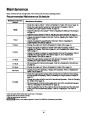
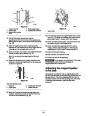
2. Apply No. 2 general purpose grease to the worm gear
(Fig. 13).
Figure 11
1
1.
2.
Handgrip
3.
Approximately 4 inches
(10.2 centimeters)
Two inches
(5
centimeters)
4.
Auger/impeller drive
control lever
2
4
6.
Press the auger/impeller drive control lever slowly
toward the handgrip.
3
Note: The amount of force needed to compress the
lever increases noticeably when you remove the slack
from the auger/impeller drive belt (approximately
one-half of the lever movement). The adjustment is
correct when the force begins to increase and the
distance between the top of the handgrip and the bottom
of the auger/impeller drive control lever is 2 inches
658
Figure 13
1.
2.
Worm gear
Bracket
3.
Bolt, pyramidal washer,
and locknut
4.
Mounting flange
(5
centimeters) as shown in Figure 11.
Note: If the force does not noticeably increase, remove
the belt cover (refer to steps 1 and 2 of Replacing the
Auger/Impeller Drive Belt on page 23) and measure
3. Loosely mount the worm gear and the bracket to the
mounting flange with a bolt, a pyramidal washer, and a
locknut as shown in Figure 13.
2
where you remove the slack from the auger/impeller
drive belt.
inches (5 centimeters) above the handgrip at the point
4.
5.
6.
Slide the worm gear into the teeth of the chute retaining
ring and tighten the locknut (Fig. 13).
Tighten the locknut that secures the chute control
bracket (Fig. 12).
7.
8.
Adjust the flange nut and the flange locknut (Fig. 10), if
necessary, to obtain the proper dimension between the
top of the handgrip and the bottom of the auger/impeller
drive control lever.
Check the operation of the chute control rod, and move
the worm gear slightly outward if it binds.
Tighten the nuts securely.
11
| Categories | Snow Blower Manuals, Toro Snow Blower |
|---|---|
| Tags | Toro 38053, Toro 521, Toro 824 Power Throw |
| Model Number | 38053 |
| Model Year | 2002 |
| Download File |
|
| Document Type | Operator's Manual |
| Language | English |
| Serial Number | 220000001 - 220999999 |
| Product Name | 824 Power Throw Snowthrower |
| Product Brand | Toro. Customer Service Representatives are available by phone:
Monday - Friday 7:30 a.m. to 9:00 p.m. (CDT) - Saturday 8:00 a.m. to 8:00 p.m. (CDT) - Sunday 10:00 a.m. to 8:00 p.m. (CDT)
Canada 1-888-225-4886 USA 1-888-384-9939, Snow Blower |
| Product Type | Snowthrower |
| Product Series | Snowthrower, Two Stage Intermediate Frame |
| Swath | 24 inch |
| Discharge | Two Stage |
| Engine Manufacturer | Tecumseh |
| Engine Motor Model # | HMSK80-155645W |
| Engine Motor Size | 8 hp |
| Engine Motor Type | 4 Cycle CARB1, EPA1 |
| Transmission Speed | 5 Forward/2 Reverse |
| Transmission Type | Friction Disc |
| Document File Type | |
| Publisher | toro.com |
| Wikipedia's Page | Toro Company |
| Copyright | Attribution Non-commercial |
(0 votes, average: 0 out of 5)