7.
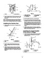
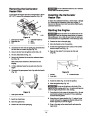
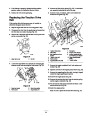
Remove the engine crankshaft bolt, lock washer, and
washer (Fig. 26).
Danger
8.
Separate and remove the engine pulley sheave (Fig. 26).
Remove the auger/impeller drive belt (Fig. 26).
Improperly adjusting the auger/impeller may
cause it to turn when disengaged. A rotating auger
or impeller can cut off or injure fingers, hands, or
feet.
9.
10.
Pull the idler pulley outward and install a new belt
around the large auger/impeller pulley (Fig. 26).
•
Keep your face, hands, feet, and any other part
of your body or clothing away from concealed,
moving, or rotating parts.
11.
Loop the belt in front of the engine pulley, and ensure
that the belt is on the inside of the idler pulley (Fig. 26).
•
•
Ensure that the impeller brake arm clearance is
maintained.
Do not adjust the auger/impeller drive belt too
tight because it may cause the auger/impeller to
turn when the control lever is in the Disengaged
position. If this occurs, decrease the belt tension.
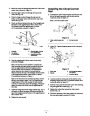
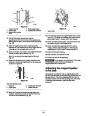
12. Install the engine pulley sheave, the washer, the lock
washer, and the engine crankshaft bolt.
Note: Ensure that the indexing rib in the engine pulley
sheave aligns with the indexing notch in the center
engine pulley. Do not pinch the belt (Fig. 27).
13.
14.
15.
16.
17.
18.
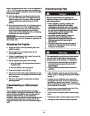
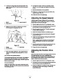
Ensure that the brake pad is properly installed on the
brake arm. Position the angled cutoff on the brake pad
as shown in Figure 28.
1.
2.
Stop the engine and wait for all moving parts to stop.
Disconnect the wire from the spark plug and ensure that
the wire does not contact the plug (Fig. 18).
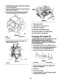
Install the 2 screws that secure the auger brake arm
assembly. Ensure that the tabs fit into the holes in the
right side of the snowthrower (Fig. 29).
3.
Check the adjustment according to steps 5 through 7 of
Installing the Auger/Impeller Drive Control Linkage on
page 10. Make any needed adjustments.
Have someone squeeze the auger/impeller drive control
lever against the handgrip, and install the belt guide
using the 2 bolts, 2 washers, and 2 lock washers.
4.
5.
6.
Connect the wire to the spark plug.
Check the belt tension by operating the auger.
Check and adjust the belt guide. Ensure that the belt
guide is about 1/8 inch (0.3 centimeters) from the belt
or the engine pulley.
If the belt still slips, replace it. Refer to Replacing the
Auger/Impeller Drive Belt on page 23.
Check and adjust the auger/impeller drive control
linkage. Refer to steps 5 through 7 of Installing the
Auger/Impeller Drive Control Linkage on page 10.
Important
and the impeller rotate when you disengage the
auger/impeller drive control lever.
Do not operate the snowthrower if the auger
Install the idler pulley spring.
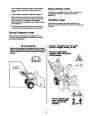
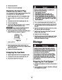
Replacing the Auger/Impeller
Drive Belt
19. Install the belt cover with the 3 bolts.
Connect the wire to the spark plug.
Do not operate the snowthrower if the auger
and the impeller rotate when you disengage the
auger/impeller drive control lever.
20.
Important
If the auger/impeller drive belt becomes worn, oil-soaked,
or otherwise damaged, replace the belt.
1.
2.
Stop the engine and wait for all moving parts to stop.
Disconnect the wire from the spark plug and ensure that
the wire does not contact the plug (Fig. 18).
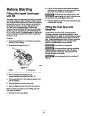
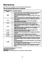
Lubricating the Snowthrower
Lightly lubricate all moving parts of the snowthrower after
every 15 operating hours and at the end of the
snowthrowing season.
3.
4.
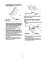
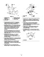
Remove the 3 bolts that hold the belt cover in place and
set the cover aside (Fig. 24).
Loosen the auger brake arm assembly by loosening the
rearmost screw and removing the front screw that fasten
the auger brake arm assembly to the frame (Fig. 25).
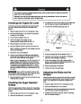
Important
Do not get oil or grease on the rubber wheel
or friction drive plate because the wheel will slip and the
rubber may deteriorate.
5.
6.
Remove the idler pulley spring (Fig. 25). Let the brake
arm assembly to hang free but out of the way.
1.
2.
Stop the engine and wait for all moving parts to stop.
Disconnect the wire from the spark plug and ensure that
the wire does not contact the plug (Fig. 18).
Remove the 2 bolts, 2 washers, and 2 lock washers that
secure the belt guide (Fig. 26).
23
| Categories | Snow Blower Manuals, Toro Snow Blower |
|---|---|
| Tags | Toro 38053, Toro 521, Toro 824 Power Throw |
| Model Number | 38053 |
| Model Year | 2002 |
| Download File |
|
| Document Type | Operator's Manual |
| Language | English |
| Serial Number | 220000001 - 220999999 |
| Product Name | 824 Power Throw Snowthrower |
| Product Brand | Toro. Customer Service Representatives are available by phone:
Monday - Friday 7:30 a.m. to 9:00 p.m. (CDT) - Saturday 8:00 a.m. to 8:00 p.m. (CDT) - Sunday 10:00 a.m. to 8:00 p.m. (CDT)
Canada 1-888-225-4886 USA 1-888-384-9939, Snow Blower |
| Product Type | Snowthrower |
| Product Series | Snowthrower, Two Stage Intermediate Frame |
| Swath | 24 inch |
| Discharge | Two Stage |
| Engine Manufacturer | Tecumseh |
| Engine Motor Model # | HMSK80-155645W |
| Engine Motor Size | 8 hp |
| Engine Motor Type | 4 Cycle CARB1, EPA1 |
| Transmission Speed | 5 Forward/2 Reverse |
| Transmission Type | Friction Disc |
| Document File Type | |
| Publisher | toro.com |
| Wikipedia's Page | Toro Company |
| Copyright | Attribution Non-commercial |
(0 votes, average: 0 out of 5)