


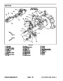

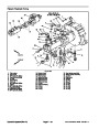
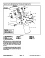

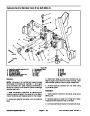
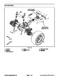
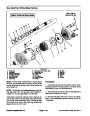


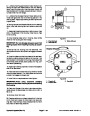

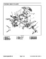


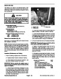
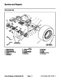
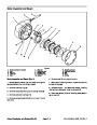


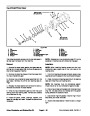
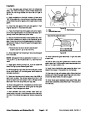
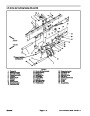


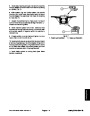
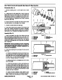

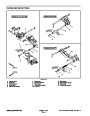


8.
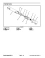
thrust bearing (13), second thrust race (12), and second
retaining ring (3) onto drive shaft (21). Position washer
Place exterior retaining ring (3), thrust race (12),
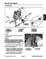
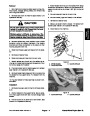
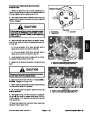
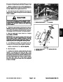
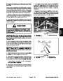
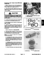
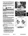
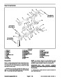
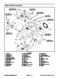
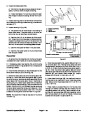
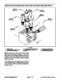
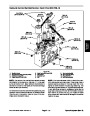
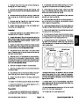
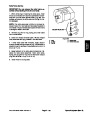
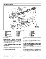
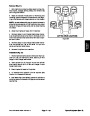
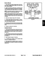
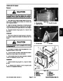
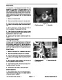
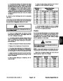
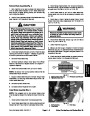
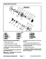
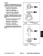
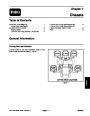
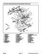
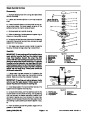
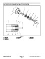
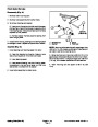
16.Apply a small amount of petroleum jelly to the steel
side of valve plate (18) to hold in place for installation.
Aligning the index pin, place the valve plate (18) in posi-
tion onto the backplate (20), with steel side against
backplate.
(24)
and shaft seal (25) onto shaft.
9.
Install shaft assembly into front ofhousing. Seat seal
(25)
retaining ring (2).
into position with seal driver and retain with interior
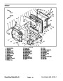
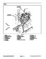
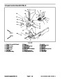
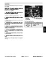
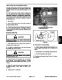
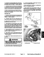
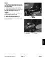
17.Install backplateassembly(20)ontohousingassem-
bly (19). Make sure ports are positioned correctly, and
that valve plate (18) and gasket (32) stay in place.
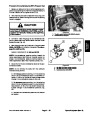
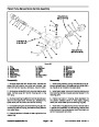
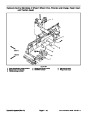
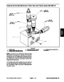
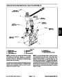
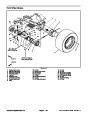
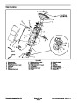
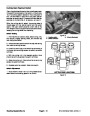
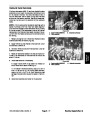
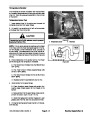
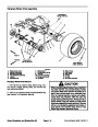
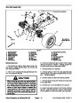
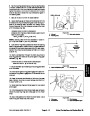
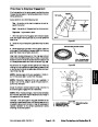
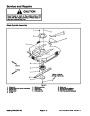
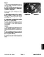
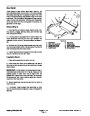
10.Install
servo piston follower (8) onto camplate dowel
pin. Install camplate (11) carefully onto bushing (44)
(coat bushing surface with hydraulic oil), aligning servo
piston follower (8) with slot in servo piston assembly (7).
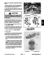
18.Retain backplate (20) with four cap screws (15).
Torque cap screws from 27 to 31 ft--lb (37 to 42 N--m).
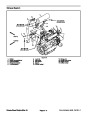
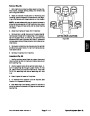
19.Install
control housing gasket (34) onto housing.
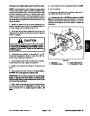
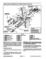
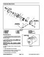
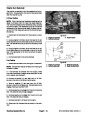
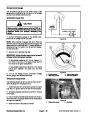
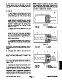
11.
Position housing in a horizontal position. Holding
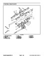
Install orifices (30) into servo control assembly (28) and
retain in position with petroleum jelly. Position the feed-
back link at 90 degrees from control housing. Install
manual servo control assembly (28) onto housing mak-
ingsurefeedback linkenteredsmallgrooveinservopis-
ton assembly (7).
camplate (11) in position with screw driver through con-
troller linkage passageway at the top of housing, place
rotatingkitassembly(6)overshaftandintohousinguntil
pistons are against camplate (11). Make sure all parts
are in housing completely and are properly positioned.
Returnthepumptothevisewithopenendofhousingup,
clamping housing on the outer portion of the flange.
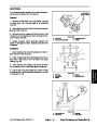
20.Secure
control assembly with six socket head
screws (17). Torque screws from 40 to 48 in--lb (4.5 to
5.4 N--m).
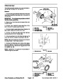
12.Install
gasket (32) onto housing.
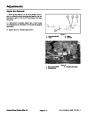
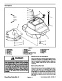
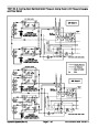
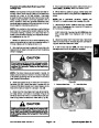
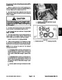
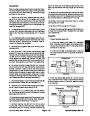
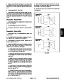
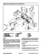
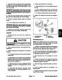
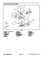
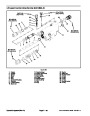
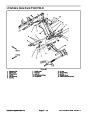
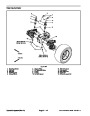
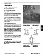
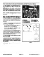
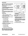
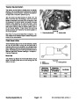
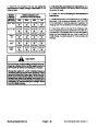
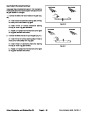
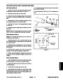
13.If
necessary, press new bearing (45) and roll pin (38)
21.Install control arm (27) onto control assembly input
shaft. Retain with lock washer (23) and nut (22). Torque
nut from 4 to 6 ft--lb (5 to 8 N--m).
inbackplate(20)todimensionshowninFigure58.Note:
Bearing should be installed with the numbered end out-
ward. Roll pin should be installed with split oriented
away from bearing.
22.Install
remaining plugs that were removed from
pump. Torque 3/4 in. plug from 21 to 24 ft--lb (28 to 32
N--m). Torque 1--1/4 in. plug from 40 to 45 ft--lb (54 to 61
N--m).
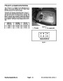
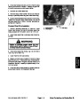
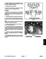
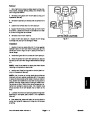
NOTE: Forward and reverse relief valves are identical.
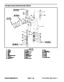
14.Install
new o--ring on relief valves (16 & 26). Install
reliefvalveinthecavityinbackplateandtorquefrom100
to 110 ft--lb (136 to 149 N--m).
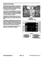
15.Install
new o--ring on bypass valve (14). Install by-
pass valve (14) into backplate (20). Note: Make sure
paddle of bypass valve is perpendicular to relief valve
axis prior to installing or damage could result.
Groundsmaster 4500--D/4700--D
Page 4 -- 67
Hydraulic System (Rev. A)
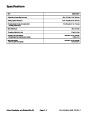
| Categories | Lawn Mower Manual, Sprinkler and Irrigation Manuals, Toro Sprinkler and Irrigation Manuals |
|---|---|
| Tags | Toro Groundsmaster 4500 D, Toro Groundsmaster 4700 D |
| Download File |
|
| Document Type | Service Manual |
| Language | English |
| Product Brand | Toro. Customer Service Representatives are available by phone:
Monday - Friday 7:30 a.m. to 9:00 p.m. (CDT) - Saturday 8:00 a.m. to 8:00 p.m. (CDT) - Sunday 10:00 a.m. to 8:00 p.m. (CDT)
Canada 1-888-225-4886 USA 1-888-384-9939, Lawn Mower |
| Document File Type | |
| Publisher | toro.com |
| Wikipedia's Page | Toro Company |
| Copyright | Attribution Non-commercial |
(0 votes, average: 0 out of 5)