


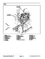


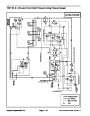

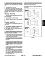

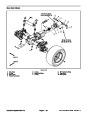


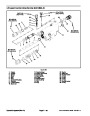


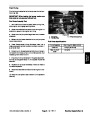
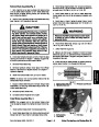


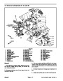


Lower Cutting Units
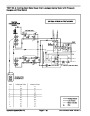
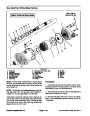
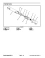
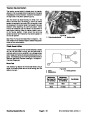
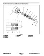
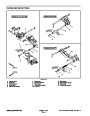
A three section gear pump is coupled to the piston (trac-
tion) pump. The gear pump section (P3) farthest from
the piston pump supplies hydraulic flow to both the lift/
lower control valve and the steering control valve. Hy-
draulic flow from this pump section is delivered to the
circuits through a proportional flow divider. This pump
section takes its suction from the hydraulic reservoir.
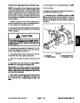
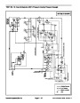
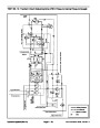
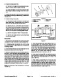
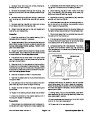
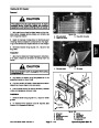
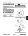
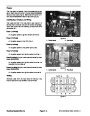
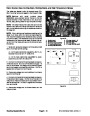
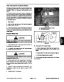
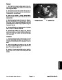
Maximum lift/lower circuit pressure (2200 PSI) is limited
by a relief valve in the power down and traction assist
control manifold (RV7).
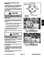
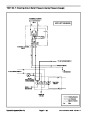
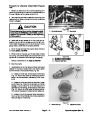
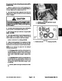
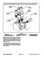
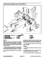
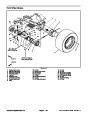
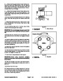
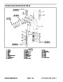
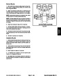
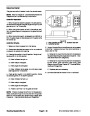
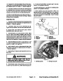
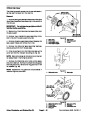
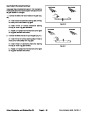
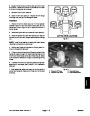
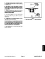
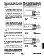
To lower a side cutting unit on the Groundsmaster
4700--D (deck #6 or #7), the appropriate lift lever on the
lift/lowercontrolvalveispushedtoallowvalveshiftinthe
lift/lower control. This valve change causes a shift in the
sequence valve located in the power down and traction
assist manifold and also allows a passage for oil flow
from the rod end of the lift cylinder. Oil flow to the piston
end of the lift cylinder causes the cylinder shaft to ex-
tend, and lowers the cutting unit. Oil from the rod end of
the cylinders returns to the traction charge circuit. When
the lift lever is released, the lift cylinder is held in posi-
tion.
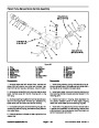
OntheGroundsmaster4500--D,asingleliftleverisused
toliftandlower thefivecuttingdecks.TheGroundsmas-
ter 4700--D has three lift levers to control the cutting
decks: the center lever is for the five center decks, the
left lever controls the left, rear deck (#6), and the right
lever controls the right, rear deck (#7).
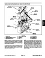
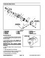
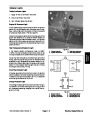
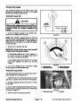
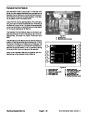
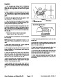
An adjustable counterbalance valve (RV1) maintains
backpressureonthedeckliftcylinders.Thiscounterbal-
ance pressure transfers cutting unit weight to the ma-
chine to improve traction. Excess circuit flow is routed to
the oil filter and then to the traction charge circuit.
Pressure to the lift/lower control valve can be monitored
at a port on the end of the gear pump.
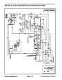
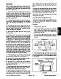
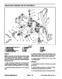
When the cutting units are in a stationary position, flow
from the gear pump is by--passed through the lift/lower
control valve, power down and traction assist control
manifold, oil filter, and traction charge circuit.
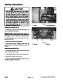
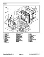
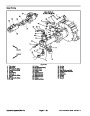
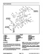
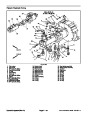
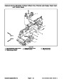
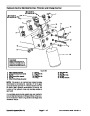
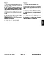
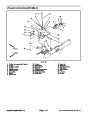
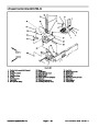
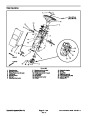
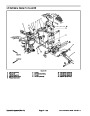
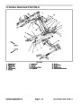
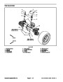
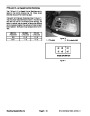
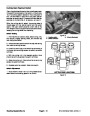
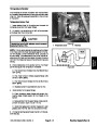
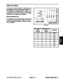
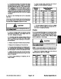
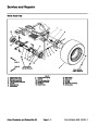
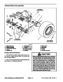
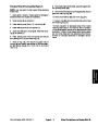
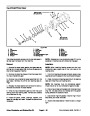
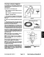
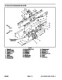
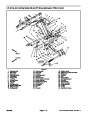
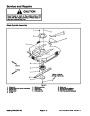
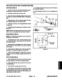
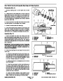
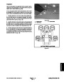
#4
Deck
#1 Deck
#5 Deck
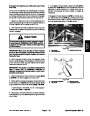
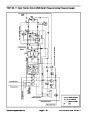
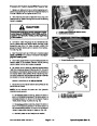
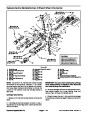
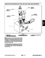
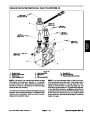
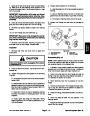
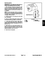
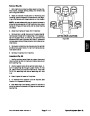
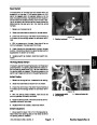
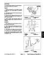
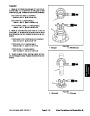
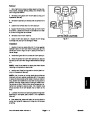
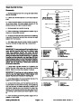
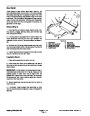
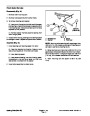
Tolower thecenter fivecutting decks, the liftlever onthe
lift/lowercontrolvalveispushedtoallowvalveshiftinthe
lift/lowercontrol.Thisvalvechangeallowsapassagefor
oil flow from the rod end of the lift cylinders. The weight
of the cutting decks causes the lift cylinders to extend,
lowering the cutting units. An orifice positioned in the lift/
lower control valve restricts oilflow from the liftcylinders
to control deck drop speed. Oil from the rod end of the
cylinders is allowed to return to the traction charge cir-
cuit. The piston end of the cylinders are replenished by
the charge circuit. When the lift lever is released, the lift
cylinders are held in position.
#
2
#3
Deck
#
6 Deck
#7 Deck
(GM4700)
Deck
(GM4700)
CUTTING DECK LOCATIONS
Figure 9
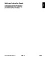
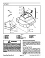
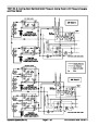
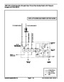
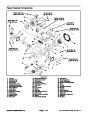
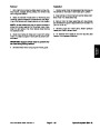
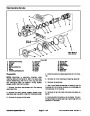
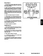
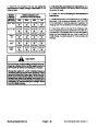
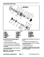
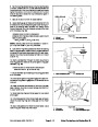
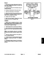
2200
PSI
GM 4700--D
LOWER DECK #6 SHOWN
Figure 10
Page 4 -- 11
Groundsmaster 4500--D/4700--D
Hydraulic System (Rev. A)
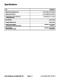
| Categories | Lawn Mower Manual, Sprinkler and Irrigation Manuals, Toro Sprinkler and Irrigation Manuals |
|---|---|
| Tags | Toro Groundsmaster 4500 D, Toro Groundsmaster 4700 D |
| Download File |
|
| Document Type | Service Manual |
| Language | English |
| Product Brand | Toro. Customer Service Representatives are available by phone:
Monday - Friday 7:30 a.m. to 9:00 p.m. (CDT) - Saturday 8:00 a.m. to 8:00 p.m. (CDT) - Sunday 10:00 a.m. to 8:00 p.m. (CDT)
Canada 1-888-225-4886 USA 1-888-384-9939, Lawn Mower |
| Document File Type | |
| Publisher | toro.com |
| Wikipedia's Page | Toro Company |
| Copyright | Attribution Non-commercial |
(0 votes, average: 0 out of 5)