


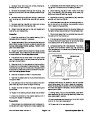


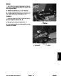


5.
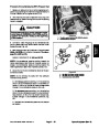
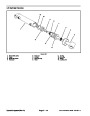
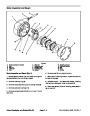
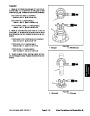
Apply Loctite #242 or equivalent to set screw (18)
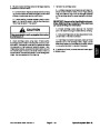
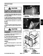
5. Test the switch by moving the control arm to the det-
entposition,thelightshouldbeon.Movethecontrolarm
out of detent, the light should go off.
and install into control housing. Adjust set screw until it
bottoms out on input shaft and back out one--quarter
turn.
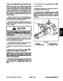
6.
Remove test light and put servo control assembly
6.
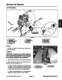
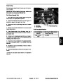
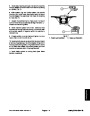
7.
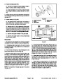
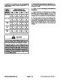
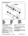
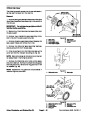
just plug until there is no end play in the valve spool with
input shaft held stationary. Secure plug in place with set
screw (24). Torque set screw from 17 to 26 in--lb (2 to 3
N--m).
Install wiper seal on input shaft.
into operation.
Install new o--ring (2) onto plug and install plug. Ad-
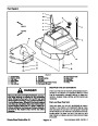
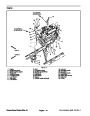
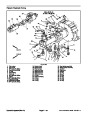
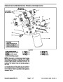
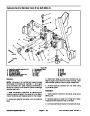
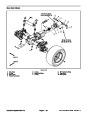
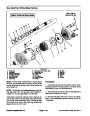
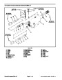
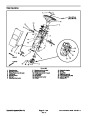
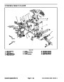
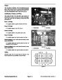
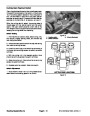
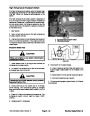
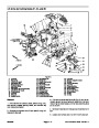
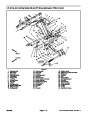
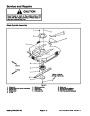
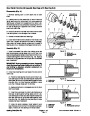
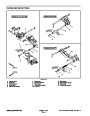
Reassembly
Step 4--C
“A”
“B”
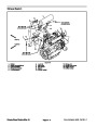
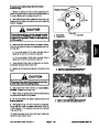
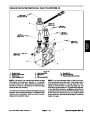
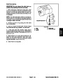
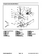
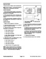
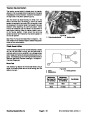
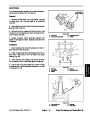
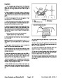
Disassembly -- Neutral Switch
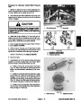
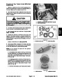
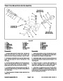
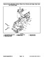
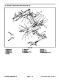
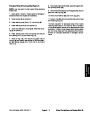
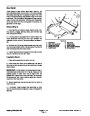
1.
Loosensetscrew(17)inadapterandremoveneutral
switch from adapter.
2.
Remove adapter from control housing.
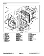
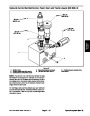
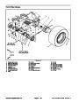
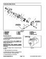
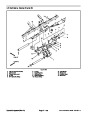
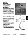
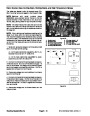
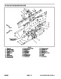
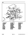
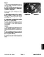
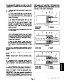
Reassembly
Step 4--D
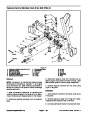
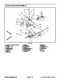
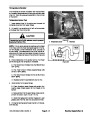
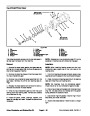
3.
Remove pin, ball, and o--rings (11 & 16) from adapt-
er.
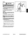
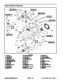
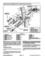
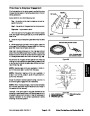
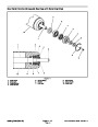
Reassembly -- Neutral Switch
Install new o--ring (11) onto adapter and new o--ring
1.
(16)
onto pin.
2.
leum jelly to hold in place during installation.
Install ball and pin into adapter. Lubricate with petro-
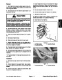
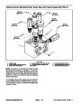
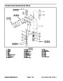
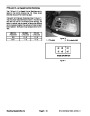
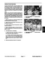
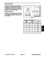
Reassembly
Step 4--E
“B”
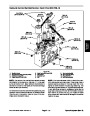
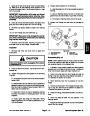
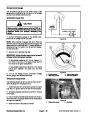
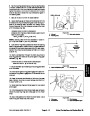
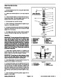
3.
Install adapter into control housing. Torque from 44
to 52 ft--lb (60 to 70 N--m).
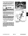
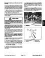
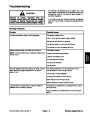
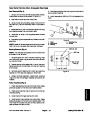
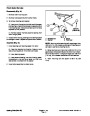
4.
switch and install switch into adapter. The adjustment
procedure for the switch are as follows.
Apply Loctite#222orequivalenttothreads ofneutral
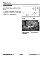
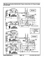
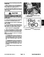
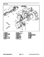
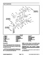
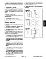
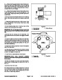
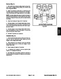
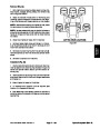
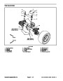
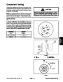
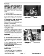
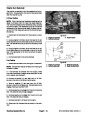
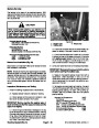
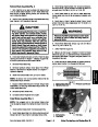
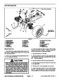
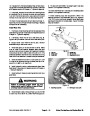
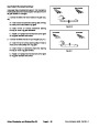
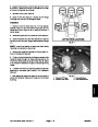
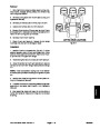
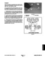
A. Install switch, while moving link back and forth,
until “detent” action is detected. Back out the switch
until the “detent” action is very slight.
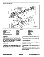
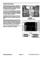
“A”
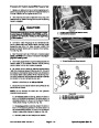
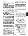
Figure 63
B. Attach the leads from a test light to the switch ter-
minals. Note: A multimeter could be used instead of
a test light.
C. Move the link out of the detent position. The test
lightwillgoon.Screw intheswitch untilthelightgoes
off. Mark this as position “A” (Fig. 63). Move the link
to the detent position and the test light should come
back on.
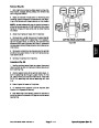
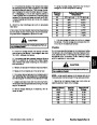
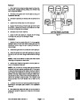
D. Leavingthelinkinthedetentposition,thelightwill
remain on.Screw in the switch until the light goes off.
Mark this position “B”.
E. Unscrew the switch one third of the distance be-
tween “B” and “A”. Install and tighten the set screw
(17)
in one of the upper quadrants of the hex of the
switch adapter (Fig. 63). Torque set screw from 28 to
in--lb (3.2 to 3.8 N--m).
34
Groundsmaster 4500--D/4700--D
Page 4 -- 69
Hydraulic System (Rev. A)
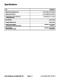
| Categories | Lawn Mower Manual, Sprinkler and Irrigation Manuals, Toro Sprinkler and Irrigation Manuals |
|---|---|
| Tags | Toro Groundsmaster 4500 D, Toro Groundsmaster 4700 D |
| Download File |
|
| Document Type | Service Manual |
| Language | English |
| Product Brand | Toro. Customer Service Representatives are available by phone:
Monday - Friday 7:30 a.m. to 9:00 p.m. (CDT) - Saturday 8:00 a.m. to 8:00 p.m. (CDT) - Sunday 10:00 a.m. to 8:00 p.m. (CDT)
Canada 1-888-225-4886 USA 1-888-384-9939, Lawn Mower |
| Document File Type | |
| Publisher | toro.com |
| Wikipedia's Page | Toro Company |
| Copyright | Attribution Non-commercial |
(0 votes, average: 0 out of 5)