


SB2040 Snowblower
Assembly and Installation
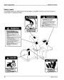
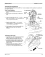
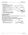
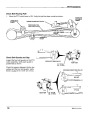
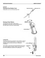
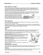
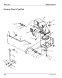
Connect Lift Rods
1.
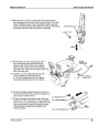
Allow the subframe to pivot (while the blower head remains stationary), so you can connect the two lift
rods to the subframe using the two 5/8 x 1-5/8" clevis pins and 4 x 80 mm spring clips.
Verify that the two counterbalance springs remain connected at both ends.
2.
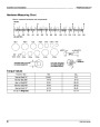
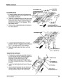
4 x 80
mm SPRING CLIP
5/8 x 1-5/8" CLEVIS PIN
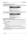
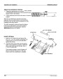
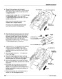
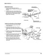
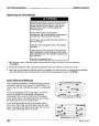
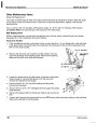
Engage Lockout Pin
The counterbalance springs transfer the weight of the push
frame (and blower head) against the subframe. This
arrangement allows the height adjustment lever to easily
raise and lower the entire blower head. The push frame
must be locked into position (using the lockout pin) before
the springs can be properly adjusted.
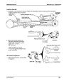
Once the counterbalance springs are adjusted, they are
under tension. The lockout pin must be kept in the locked
position until the entire snowblower is fully installed.
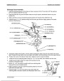
1.
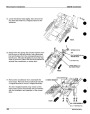
Place a suitable block of wood or other support under
the push frame, so the subframe can pivot downward.
2.
Adjust the position of the subframe as needed to slide
the lockout pin through the push frame and into the
corresponding hole in the subframe. Secure the lockout
pin with a 3 x 65 mm spring clip.
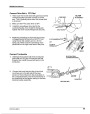
3.
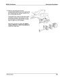
Verify the lockout pin is correctly installed by attempting
to pivot the subframe on the push frame.
POP 52152 (9610)
11
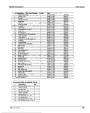
| Categories | Honda Snow Blower Manuals, Snow Blower Manuals |
|---|---|
| Tags | Honda SB2040 |
| Download File |
|
| Document Type | Owner's Manual |
| Language | English |
| Product Brand | Honda, Snow Blower |
| Document File Type | |
| Publisher | hondapowerequipment.com |
| Wikipedia's Page | Honda |
| Copyright | Attribution Non-commercial |
(0 votes, average: 0 out of 5)