


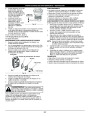


MAINTENANCE AND REPAIR INSTRUCTIONS
5.
Clean the shaft and the inner surface of the outer spool.
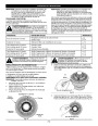
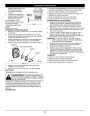
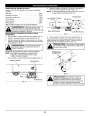
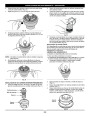
3.
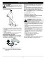
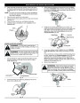
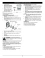
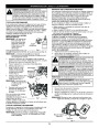
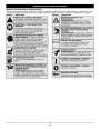
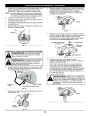
While holding the locking rod, loosen the nut on the blade
by turning it clockwise with a 5/8 inch wrench (Fig. 34). Re-
move the nut, retaining washer and blade. Keep the nut and
blade retainer for installation.
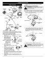
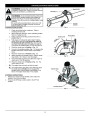
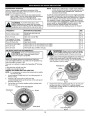
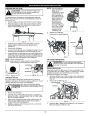
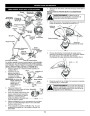
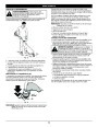
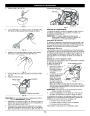
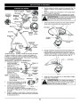
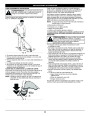
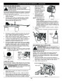
To clean the shaft underneath the plunger, press down on
the plunger (Fig. 31). Remove any dirt or debris from the
shaft.
NOTE: The inner reel must be totally dry before reinstalling it
into the outer spool. Do not lubricate the inner reel or
outer spool assembly.
6.
7.
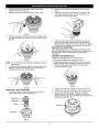
Place the inner reel into the outer spool.
Place the bump knob, spring and foam seal onto the inner
reel (Fig. 27).
Loosen
8.
9.
Press the bump knob down and tighten clockwise.
Install new line as described in Line Installation for the
SpeedSpool®.
Fig. 34
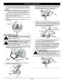
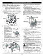
4.
Install the new blade, blade retainer and nut (Fig. 35).
Insert the locking rod through the slot into the output shaft
hole. Make sure that the blade stays flat and centered
against the output shaft while tightening the lock nut
counterclockwise (Fig. 36).
Shaft
Plunger
Edger Blade
Lock Nut
Blade Retainer
Fig. 31
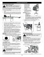
EDGER BLADE REPLACEMENT
WARNING:
To avoid serious personal injury,
always wear gloves while handling, removing or in-
stalling the blade.
Locking Rod
Fig. 35
5.
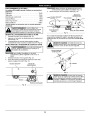
If you have a torque wrench, tighten the nut to 325-335
in.•lbs (37-38 N•m), while holding the locking rod in the
slot.
WARNING:
The gear housing gets hot after long
periods of use. To avoid serious personal injury, do
not touch the housing until it has cooled.
If you do not have a torque wrench, hold the locking rod in
the slot. Rotate the nut counterclockwise with a 5/8 inch
closed-ended or socket wrench, until the nut presses
against the washer and the blade is snug. Make sure the
blade assembly is installed correctly, then rotate the nut an
additional 1/4-1/2 turn (Fig. 36).
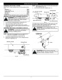
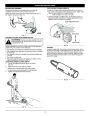
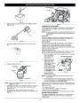
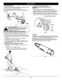
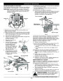
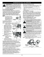
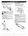
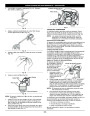
1.
Line up the hole in output shaft with the locking rod slot.
Insert the locking rod through the slot into the output
shaft hole (Fig. 32).
6.
Remove the locking rod.
Output Shaft
Hole
WARNING:
Verify that the blade is flat against
the output shaft after the nut is tightened. If the
blade is off-center, the unit will vibrate excessively
and may damage. Also, the blade may dislodge
and fly off, possibly causing serious personal injury.
Output Shaft
Locking Rod
Locking Rod Slot
Fig. 32
Tighten
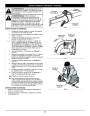
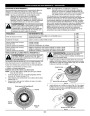
2.
Hold the locking rod in place by grasping it next to the
boom of the unit (Fig. 33).
Fig. 36
Locking
Rod
Fig. 33
12
| Categories | Lawn Mower Manual, MTD Lawn Mower Manuals, MTD Trimmer Manuals, Trimmer Manuals, Troy-Bilt Lawn Mower Manuals |
|---|---|
| Tags | MTD TB525ET, Troy-Bilt TB525ET |
| Download File |
|
| Document Type | Owner's Manual |
| Language | English |
| Product Brand | MTD, Lawn Mower |
| Product Type | Walk Behind Mower |
| Document File Type | |
| Publisher | mtdproducts.com |
| Wikipedia's Page | MTD Products |
| Copyright | Attribution Non-commercial |
(0 votes, average: 0 out of 5)