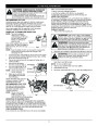


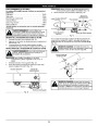


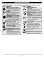


MAINTENANCE AND REPAIR INSTRUCTIONS
NOTE: Inspect the valve to rocker arm clearance with a feeler
gauge after the first 10 hours of operation and every
hours of operation.
If these statements are not true, repeat this step.
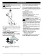
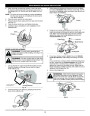
7.
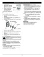
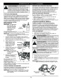
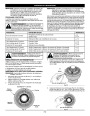
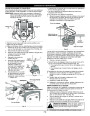
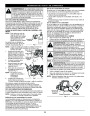
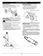
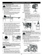
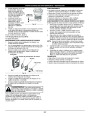
Slide the feeler gauge between the rocker arm and the
valve return spring. Measure the clearance between the
valve stem and rocker arm (Fig. 51). Measure both the
intake and exhaust valves.
25
•
The engine must be cold when checking or adjusting the
valve clearance.
•
This task should be performed inside, in a clean, dust free
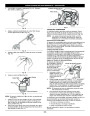
The recommended clearance for both intake and exhaust is
.003 – .006 in. (.076 – 0.152 mm). Use a standard automotive
.005 in. (0.127 mm) feeler gauge. The feeler gauge should slide
between the rocker arm and valve stem with a slight amount of
resistance, without binding. See Figures 51 and 52.
area.
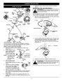
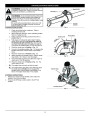
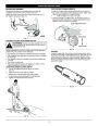
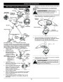
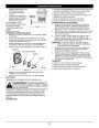
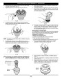
1.
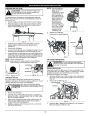
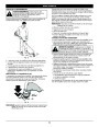
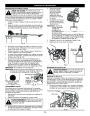
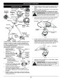
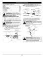
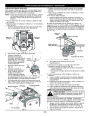
Remove the six (6) screws on the back of the engine cover
with a Flat-head or T-25 Torx screwdriver (Fig. 49).
View Of The Rear Engine Cover
Adjusting Nut
Rocker Arm
Remove
Screws
Remove
Screws
.003–.006 in.
(.076–.152 mm)
Feeler Gauge
Valve Stem
Fig. 49
2.
3.
Disconnect the spark plug wire.
Clean dirt from around the spark plug. Remove the spark
plug from the cylinder head by turning a 5/8 in. socket
counterclockwise.
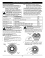
Fig. 52
If the clearance is not within specification:
8.
4.
5.
Remove the engine cover (Fig. 49).
a. Turn the adjusting nut using a 5/16 inch (8 mm) wrench or
nut driver (Fig. 52).
To increase clearance, turn the adjusting nut
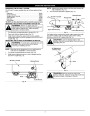
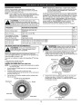
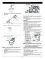
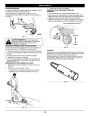
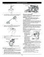
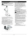
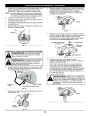
Clean dirt from around the
rocker arm cover. Remove
the screw holding the rocker
arm cover with a large flat
blade screwdriver or Torx T-
bit (Fig. 50). Remove the
rocker arm cover and gasket.
Pull the starter rope slowly to
bring the piston to the top of
its travel, (known as top dead
center). Check that:
The piston is at the top of
its travel while looking in
the spark plug hole (Fig. 50)
Both rocker arms move
freely, and both valves are
closed
•
Rocker
counterclockwise.
Arm
•
To decrease clearance, turn the adjusting nut clockwise.
b. Recheck both clearances, and adjust as necessary.
Reinstall the rocker arm cover using a new gasket. Torque
Cover
25
9.
6.
the screw to 20–30 in•lb (2.2–3.4 N•m).
Spark
Plug
Hole
10.
Check the spark plug and reinstall. See Replacing the
Spark Plug.
11.
12.
Replace the spark plug wire.
•
Reinstall the engine cover. Check alignment of the cover
before tightening the screws. Tighten screws.
REPLACING THE SPARK PLUG
•
Fig. 50
Use a replacement part number 753-05255 spark plug. The
correct air gap is 0.025 in. (0.635 mm.). Remove the plug after
every 25 hours of operation and check its condition.
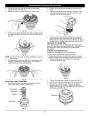
Adjusting Nuts
INTAKE
Rocker Arms
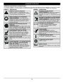
WARNING:
Do not sand blast, scrape or clean
electrodes. Grit in the engine could damage the
cylinder.
1.
Stop the engine and allow it to cool. Remove the six (6)
screws on the back of the engine cover with a Flat-head
or T-25 Torx screwdriver (Fig. 49).
EXHAUST
2.
3.
Grasp the plug wire firmly and pull the cap from the spark
plug.
Clean dirt from around the spark plug. Remove the spark
plug from the cylinder head by turning a 5/8 in. socket
Feeler Gauge
Spark Plug
Hole
Fig. 51
15
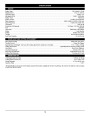
| Categories | Lawn Mower Manual, MTD Lawn Mower Manuals, MTD Trimmer Manuals, Trimmer Manuals, Troy-Bilt Lawn Mower Manuals |
|---|---|
| Tags | MTD TB525ET, Troy-Bilt TB525ET |
| Download File |
|
| Document Type | Owner's Manual |
| Language | English |
| Product Brand | MTD, Lawn Mower |
| Product Type | Walk Behind Mower |
| Document File Type | |
| Publisher | mtdproducts.com |
| Wikipedia's Page | MTD Products |
| Copyright | Attribution Non-commercial |
(0 votes, average: 0 out of 5)