


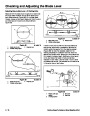


Checking and Adjusting the Blade Level
4.
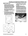
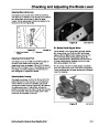
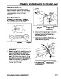
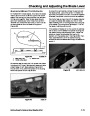
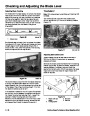
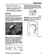
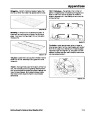
Measure from the front blade tip to the ground,
mark that tip with tape for future reference and
rotate it 180 degrees to the rear and measure from
the tip to the ground. If the tip in the front is not
7.
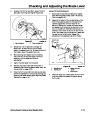
After adjusting both eyebolt lock nuts evenly,
check the front-to-rear pitch again. Continue
adjusting the eyebolts until the front blade tip is
0-5/16 inch (0-8mm) lower than in the rear.
0-5/16
inch (0-8mm) lower than in the rear,
8.
9.
When the front-to-rear pitch is correct, tighten the
pivot plate mounting bolts.
adjustment is necessary (Figure 46).
Check the side-to-side level to assure that has not
changed. Correct if needed (see “Adjusting
Side-to-Side Level—All Cutting Units” on page
4-10).
10.
11.
Check gage wheel height. Each wheel should be
approximately 3/8 inch (9.5mm) off the ground.
Adjust as needed.
Once the front-to-rear pitch and side-to-side level
are within specification, continue by checking and
adjusting the blade tracking, as follows.
Adjusting Blade Tracking
The 32-inch (81.3cm) cutting unit requires a blade
tracking adjustment procedure different from the
procedure required for the 38-inch (96.5cm) and the
44-inch (111.7cm) cutting units. Use the procedure, as
follows, appropriate to the cutting unit on which you are
working.
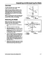
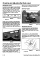
Figure 46
3. Measure rear blade tip
4. Measure here
XL44pit2.TIF
1.
Blade front to rear
Measure front blade
tip
2
.
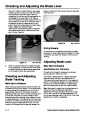
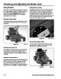
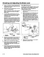
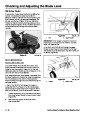
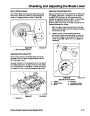
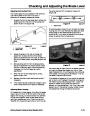
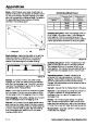
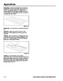
5.
To adjust the front-to-rear pitch, loosen the front
mounting plate bolts slightly (Figure 47).
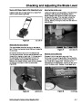
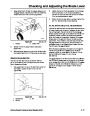
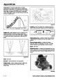
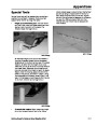
32-inch (81.3cm) Cutting Unit
The blade should be a minimum of 1/8 inch (3.1mm)
above the bottom of the housing. If it is not, you may
adjust it by inserting a washer or other shim between
the spindle housing and mower housing. Re-measure
the blade side to side. If now correct, remove the
spindle-housing bolt and re-install through the housing,
shim, and spindle. Note that the blade tip will move
more than the thickness of the shim. This adjustment is
to ensure the blade travels in an even plane at an even
distance above the bottom of the mower housing.
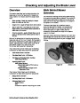
Figure 47
XL44pit3.TIF
Eyebolt locknut
1.
Pivot mounting bolt
2.
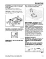
6.
Rotate the lock nuts on the eyebolts to change the
adjustment. To raise the front of the mower,
tighten the eyebolt lock nuts. To lower the front of
the mower, loosen the eyebolt lock nuts.
4 - 14
Service Dealer’s Guide to Great Quality of Cut
| Categories | Lawn Mower Manual, Toro Lawn Mower Manual |
|---|---|
| Model Year | 2002 |
| Download File |
|
| Document Type | Workshop Manual |
| Language | English |
| Product Name | Toro Lawnmower |
| Product Brand | Toro. Customer Service Representatives are available by phone:
Monday - Friday 7:30 a.m. to 9:00 p.m. (CDT) - Saturday 8:00 a.m. to 8:00 p.m. (CDT) - Sunday 10:00 a.m. to 8:00 p.m. (CDT)
Canada 1-888-225-4886 USA 1-888-384-9939, Lawn Mower |
| Product Type | Walk Behind Mower |
| Engine Manufacturer | Briggs & Stratton |
| Engine Motor Type | 2 Cycle, 2 Cycle CARB1, 2 Cycle EPA1, 2 Cycle EPA2, 4 Cycle |
| Transmission Type | Hand Push |
| Document File Type | |
| Publisher | toro.com |
| Wikipedia's Page | Toro Company |
| Copyright | Attribution Non-commercial |
(0 votes, average: 0 out of 5)