

SECTION 5: ASSEMBLY INSTRUCTIONS
This operator’s manual covers various models of
snow throwers. The units illustrated may vary slightly
from your unit. Follow only those instructions which
pertain to your model snow thrower.
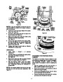
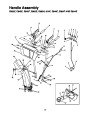
Attaching the Handle Assembly.
(Hardware A and E)
Lay loose parts out on flat surface.
1.
2.
Handle Panel
Right Handle
5. Traction Control
Grip
IMPORTANT: After assembly, service engine with
gasoline, and check oil level as instructed in the
separate engine manual packed with your unit.
6.
7.
Right Grip Bracket
Left Grip Bracket
3. Left Handle
NOTE: All references to right or left side of the
snow thrower are determined from behind the unit in
the operating position.
4. Auger Control Grip
1
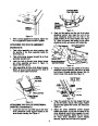
UNPACKING
1.
Remove staples or break glue on the top flaps of
the carton. Remove any loose parts like
operator’s manual or hardware pack included
with unit.
7
6
5
4
2.
3.
4.
5.
Cut corner’s and lay end of carton down flat.
Remove packing material.
Roll unit out of carton. Check carton thoroughly
for loose parts.
Extend cables out behind unit and lay them on
the floor.
2
3
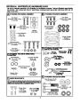
Lay out the contents of the hardware pack
according to the illustration in section 4 and
identify each part.
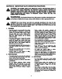
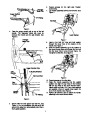
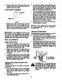
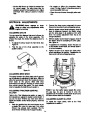
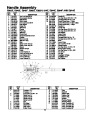
Figure 3
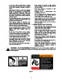
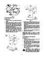
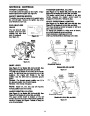
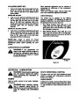
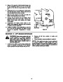
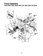
1.
Attach left handle and left grip bracket to handle
panel with two carriage bolts, lock washers and
hex nuts. (Be sure the bend in the grip bracket is
towards the center of the handle panel. (See
Figure 4.) Do not tighten at this time.
6.
Find the loose parts in the carton and lay these
on the floor. See Figure 3. You should locate the
following loose parts in the carton:
1.
2.
3.
4.
5.
6.
7.
8.
9.
Handle Panel
Right Handle
Left Handle
Auger Control Grip
Traction Control Grip
Right Clutch Grip Bracket
Left Clutch Grip Bracket
Shift Rod (Not Illustrated)
Chute Directional Control Assembly
(Not Illustrated)
Outer
Handle Panel
Edge
Left Grip Bracket
of Handle
Panel
Carriage
Bolts
Hex Nuts
10.
11.
Chute Assembly (Not Illustrated)
Hardware Pack (Not Illustrated)
Left Handle
(curves in)
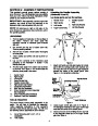
TOOLS REQUIRED
Lock Washers
The snow thrower comes partly assembled in the
carton. You will have to complete the assembly.
Follow assembly instructions in this operator’s
manual to make the job safe and easy. You will need
the following tools to assemble the snow thrower.
Figure 4
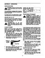
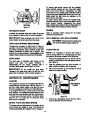
2.
3.
Locate auger control grip, part #4 in Figure 3.
The triangular metal tab on the auger control grip
must face the center of the handle panel.
Insert curved end of the Z fitting into the top hole
in the triangular metal tab on the auger control
grip. See Figure 5.
A.
B.
Set of Wrenches (3/8", 9/16", 1/2" or
adjustable)
Pair of pliers
6
| Categories | MTD Snow Blower Manuals, Snow Blower Manuals, Yard Machines Snow Blower Manuals |
|---|---|
| Tags | MTD 614E, MTD E602E, MTD E642EE642F, MTD E644E, MTD E662E, MTD E662H, MTD E664F, MTD E6A4E, MTD Snow Blower Manual, Yard Machines 614E, Yard Machines E602E, Yard Machines E642EE642F, Yard Machines E644E, Yard Machines E662E, Yard Machines E662H, Yard Machines E664F, Yard Machines E6A4E |
| Download File |
|
| Document Type | Owner's Manual |
| Language | English |
| Product Brand | Yard Machines, 614E, E602E, E642EE642F, E644E, E662E, E662H, E664F, E6A4E, Snow Blower |
| Document File Type | |
| Publisher | mtdproducts.com |
| Wikipedia's Page | MTD Products |
| Copyright | Attribution Non-commercial |
(0 votes, average: 0 out of 5)