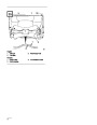

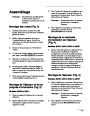


Assembly
4.
Secure chute and handle to remaining holes in
chute ring and tighten all nuts SECURELY.
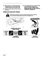
Note:
Determine left and right sides of the
snowthrower by standing in the normal
operator’s position behind the handles.
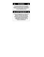
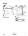
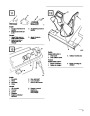
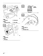
Install Chute Crank (Fig. 4)
Models 38422, 38424, 38432 & 38437
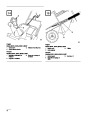
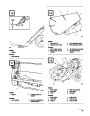
Install Wheels (Fig. 2)
1.
Insert flattened end of chute crank through hole
in shroud while aligning mounting bracket with
holes in lower handle. Slowly rotate crank until
flattened end fits into hidden gear opening and
chute ring turns with crank. Make sure plastic
bushing is fully inserted into hole in mounting
bracket, then secure mounting bracket to handle
with (2) capscrews and locknuts.
1.
Carefully turn machine onto its left side. Place a
wood block under the left axle end.
2.
Slide the short spacer and a wheel onto the right
axle end. The side of the wheel with six spokes
must face the center of the machine.
3.
4.
Slide a pushnut onto the end of the axle.
Install Discharge Chute (Fig. 5)
Using a hammer, strike the pushnut to seat the
nut FIRMLY in place.
Models 38422, 38424, 38432 & 38437
1.
Set discharge chute onto chute ring. Align hole
in back of chute with center hole in ring and
install a carriage bolt and sems locknut. Position
nut on outside of chute.
5.
6.
Turn the machine over on its right side so that
the left axle end is pointing up.
For the left side, slide the long spacer and a
wheel onto the left axle end. The side of the
wheel with six spokes must face the center of the
axle.
Note:
Chute ring may be rotated to ease
assembly of discharge chute.
2.
Secure chute to remaining holes in chute ring
and tighten all nuts SECURELY.
7.
Place a wood block under the right axle end.
Repeat steps 3 and 4.
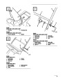
Install Handle
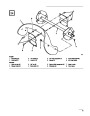
Install Discharge Chute And
Chute Handle (Fig. 3)
1.
2.
3.
Remove tie securing control cable to lower
handle.
Position upper handle so that control bar is on
top of handle, not underneath it.
Models 38409 & 38414
1.
2.
Place chute handle over chute ring.
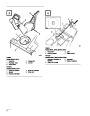
Models 38409 & 38414 – Secure upper handle
in place with (3) handle bolts, (1) eyebolt, and
Insert discharge chute between chute ring and
chute handle. Align holes.
(4)
lock nuts. Use eyebolt to mount upper left
side of handle. Eyebolt must be positioned
perpendicular to handle when tightened (Fig. 6).
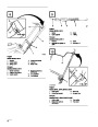
3.
Secure back of chute and handle to center hole in
chute ring with a carriage bolt and lock nut.
Position nut on outside of chute.
Models 38422, 38424, 38432 & 38437 – Secure
upper handle in place with (2) handle locks,
(1)
cable guide, (2) curved washers and (2)
Note:
Chute ring may be rotated to ease
assembly of discharge chute.
knobs. Cable guide must be perpendicular to
handle with loop facing out and up (Fig. 7).
EN–5
| Categories | Snow Blower Manuals, Toro Snow Blower |
|---|---|
| Tags | Toro 38432, Toro 38437, Toro CCR 3000 |
| Model Number | 9900001 - 9999999 |
| Model Year | 1999 |
| Download File |
|
| Document Type | Operator's Manual |
| Language | English, Français |
| Product Name | Toro CCR 3000 Snowthrower |
| Product Brand | Toro. Customer Service Representatives are available by phone:
Monday - Friday 7:30 a.m. to 9:00 p.m. (CDT) - Saturday 8:00 a.m. to 8:00 p.m. (CDT) - Sunday 10:00 a.m. to 8:00 p.m. (CDT)
Canada 1-888-225-4886 USA 1-888-384-9939, Snow Blower |
| Product Type | Snowthrower |
| Product Series | CCR 2000/3000/3600, Snowthrower |
| Swath | 20 inch |
| Discharge | Single Stage |
| Engine Manufacturer | Toro |
| Engine Motor Model # | Toro 2 cycle / NMMA-TCW3 |
| Engine Motor Size | 6 hp |
| Engine Motor Type | 2 Cycle EPA1 |
| Document File Type | |
| Publisher | toro.com |
| Wikipedia's Page | Toro Company |
| Copyright | Attribution Non-commercial |
(0 votes, average: 0 out of 5)