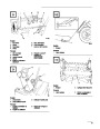


Assembly
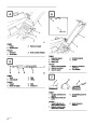
Install Handle (Fig. 4)
1.
2.
3.
Remove tie securing control cable to lower
handle.
Note:
Determine left and right sides of
snowthrower by standing in the normal
operating position.
Slide handle ends through openings in shroud
and onto lower handles inside shroud.
Secure right side of handle with (2) machine
screws. Secure left side of handle with (1)
machine screw, (1) eyebolt, and a spacer. Use the
eyebolt to mount upper left side of handle. Insert
the eyebolt through the spacer before using it to
secure handle to the snowthrower frame. The
eyebolt must be positioned perpendicular to
handle when tightened.
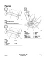
Install Wheels (Fig. 2)
1.
Place a wood block under the wheel axle for
support.
2.
Slide a spacer and wheel onto the axle. The side
of the wheel with six spokes must face the center
of the axle. Slide a pushnut onto the end of the
axle.
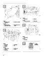
Install Control Cable (Fig. 5-6)
1.
2.
3.
Route control cable through eyebolt on left side
of snowthrower.
3.
Using a hammer, strike the pushnut to seat the
nut firmly in place. Repeat steps 2–3 for the
other wheel.
Hook spring to round hole at end of cable
adjuster (Fig. 5).
Route cable through elongated hole in cable
adjuster. Insert Z fitting on end of cable into 3rd
hole on cable adjuster (Fig. 5).
Install Discharge Chute And
Chute Handle (Fig. 3)
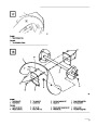
4.
Slide spring cover over spring and cable adjuster.
Push spring end through hole at end of spring
cover.
1.
2.
Place chute handle over chute ring.
Insert discharge chute between chute ring and
chute handle. Align holes.
5.
6.
Hook spring into top hole of control bar bracket
(Fig. 6).
3.
4.
Secure back of chute and handle to center hole in
chute ring with a carriage bolt, washer, and
locknut. Position washer and nut on outside of
chute.
Move control bar back toward handle until slack
in cable is removed. The gap between the control
bar bracket and handle should be approximately
1/16”–1/8”.
See insert, Figure 6. If an
adjustment is required, refer to Adjusting
Control Bar, page 10.
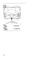
Note:
Chute ring may be rotated to ease
assembly of discharge chute.
Note:
The control cable must always have
slack in it when in the disengaged
position.
Secure chute and handle to remaining holes in
chute ring and tighten all nuts securely.
EN-5
| Categories | Snow Blower Manuals, Toro Snow Blower |
|---|---|
| Tags | Toro 38400, Toro 38405, Toro CCR 1000 |
| Model Number | 38405 |
| Model Year | 2000 |
| Download File |
|
| Document Type | Operator's Manual |
| Language | Français |
| Serial Number | 200000001 - 200999999 |
| Product Name | Toro CCR 1000 Snowthrower |
| Product Brand | Toro. Customer Service Representatives are available by phone:
Monday - Friday 7:30 a.m. to 9:00 p.m. (CDT) - Saturday 8:00 a.m. to 8:00 p.m. (CDT) - Sunday 10:00 a.m. to 8:00 p.m. (CDT)
Canada 1-888-225-4886 USA 1-888-384-9939, Snow Blower |
| Product Type | Snowthrower |
| Product Series | CCR 1000/2400/2500, Single Stage, Snowthrower |
| Swath | 20 inch |
| Discharge | Single Stage |
| Engine Manufacturer | Tecumseh |
| Engine Oil Type | Toro 2 cycle / NMMA-TCW3 |
| Engine Motor Model # | HSK635-1721A |
| Engine Motor Size | 3.5 hp |
| Engine Motor Type | 2 Cycle EPA1 |
| Document File Type | |
| Publisher | toro.com |
| Wikipedia's Page | Toro Company |
| Copyright | Attribution Non-commercial |
(0 votes, average: 0 out of 5)