

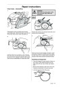


Repair instructions
Appendix A
Basic adjustment for EPA II carburetors 5. Let the engine run at ”B” rpm ~ 1 minute, until warm.
After replacing the carburetor or high speed and/or low
speed needle on an EPA (The US Environmental Protec-
tion Agency) certified product a basic adjustment must
be carried out as described below in order to meet the
EPA-requirements. This to achieve as low emissions
as possible. This instruction is made for USA & Canada
only. On EPA carburetors both the H- and L-needles are
fitted with caps to prevent the chain saw operator from
changing the adjustment above EPA standard. The caps
can be removed to achieve richer or leaner adjustments.
To set the needles correctly an adjustment sleeve is fitted
from the factory over the caps to lock them in maximum
allowed settings.
6. Adjust the H-needle to a top speed of ”C” rpm.
Model
340/345/350/351
346XP
C = 13 700
C = 14 300
7.
Check that the H-cap is still adjusted to its richest set-
ting. (Turned counterclockwise to stop). NOTE! The
H-needle must not rotate!
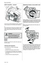
8.
Gently knock the H-cap into position. Use a 5 mm/0.2
inch mandrel (for ex. the locking pin for the bevel gear
ref.no. 502 02 61-03). This is a basic carburetor adjust-
ment. Further fine adjustments, within the limits the
caps allow, may be necessary to achieve optimum
performance. See the Operator’s manual.
When correctly set the caps must be fixed on the
needles. The adjustment sleeve then can be removed.
Over the caps on complete sparepart carburetor, there
is a plastic sleeve which is intended to lock the caps at
the richest position (anticlockwise towards stop) during
the time that the needles are adjusted. When the adjust-
ment is complete and the caps have been fixed on the
needles, the sleeve is no longer of any function and can
be removed.
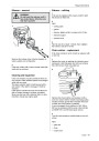
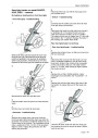
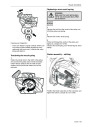
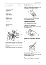
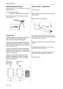
Replacement of the L-needle
1.
Take off the cap from the L-needle using e.g. a pair of
cutting pliers and unscrew the needle.
2.
Screw the new L-needle to the bottom and then turn it
counterclockwise ”D” turns.
Model
340/345/350
346XP/351
D = 1 1/2
D = 1 1/2
NOTE! On the complete spare part carburetor, the L-
needle is adjusted from the factory.
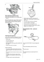
3.
Press a new L-cap on the L-needle to the first stop,
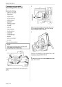
NOTE! Before making any adjustments the following
must be done!
which means that the cap is not fixed to the needle, it
should rotate independently.
•
Mount, for this model, approved bar & chain combina-
tion (See Technical data in the Operator’s manual).
4.
5.
Adjust the L-cap to the richest position (turned counter-
clockwise to stop) without turning the needle.
Model
340/345/350
346XP/351
Let the engine run at ~ ”E” app.1 minute until warm
and then let it run on idle.
16”
16”
Model
340/345/350/351
346XP
•
The chain should not be tensioned more than that it
remains ~0,2 inches to the bar.
E = 12 000
E = 13 000
•
Mount a new air filter.
6.
Adjust the idle speed to ”F” rpm.
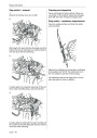
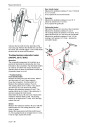
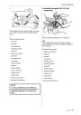
Replacement of the H-needle or complete carburetor
Model
340/345/350
346XP/351
1.
Screw the new H-needle to the bottom and turn it
counterclockwise ”A” turns.
F = 2 700
F = 2 700
Model
340/345/350
346XP/351
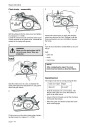
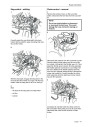
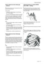
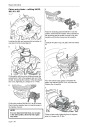
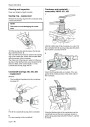
7.
Adjust the L- needle until the highest possible idling
speed is achieved and then turn the
L-needle 1/2 turn counterclockwise. Use a narrow
blade screwdriver w. ref.no. 531 00 48-63 and insert
through the hole in the cap (max. blade width 2
mm/0.08 inch) .
A = 3/4
A = 3/4
2.
Check that:
The H-cap is adjusted to its richest setting. (Turned
counterclockwise to stop). The cap is not fixed to the
needle, it should rotate independently. Adjust the
L-cap to a center position (1/4 turn counterclockwise =
minimum, 1/4 turn clockwise = maximum).
NOTE! If the chain rotates, turn the idling speed
screw (T) counterclockwise until the chain stops.
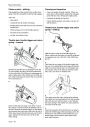
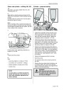
8.
Check that the L-cap is still adjusted to its richest posi-
tion. (Turned counterclockwise to stop).
3.
4.
Start the engine. If necessary, adjust the idling speed
with the T-screw until the chain stops.
NOTE! The L-needle must not rotate!
Adjust the H-needle to give a top speed of ”B” rpm.
9.
Gently knock the L-cap into position. Use a 5 mm/0.2
inch mandrel (for ex. the locking pin for the bevel gear
ref.no. 502 02 61-03).
Model
340/345/350/351
346XP
B = 12 000
B = 13 000
This is a basic carburetor adjustment. Further fine adjust-
ments, within the limits the caps allow, may be necessary
to achieve optimum performance. See the Operator’s
manual.
Use a narrow blade screwdriver (Ref.no. 531 00 48-63)
and insert it through the hole in the cap (max. blade width
2
mm/0.08 inch).
English – 51
| Categories | Chainsaw Manuals, Husqvarna Chainsaw Manuals |
|---|---|
| Tags | Husqvarna 340, Husqvarna 345, Husqvarna 346XP, Husqvarna 350, Husqvarna 351, Husqvarna 353 |
| Model Year | 2003, 2004, 2005, 2006 |
| Download File |
|
| Document Type | Operator's Manual |
| Language | English |
| Product Brand | Husqvarna, Chainsaw |
| Document File Type | |
| Publisher | husqvarna.com |
| Wikipedia's Page | Husqvarna |
| Copyright | Attribution Non-commercial |
(0 votes, average: 0 out of 5)