


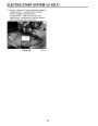
PIVOTING ZONE START BRAKE
PIVOTING ZONE START BRAKE
(DuraForce Engines Only)
Operation
The pivoting style zone brake system has two main
functions. The first function of the system is to stop the
production of spark and the second is to stop the
engine and the blade.
Introduction
In 1982, the federal government mandated that all
consumer walk behind mowers with a cut of 25" (63.5
cm) or less be equipped with safety devices. There are
two primary criteria which these devices must meet:
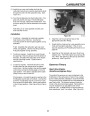
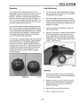
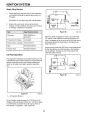
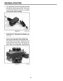
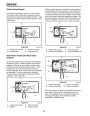
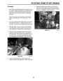
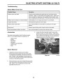
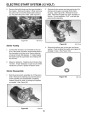
Stopping spark production is controlled by a switch.
The switch is closed when the blade control bail is in
the “at rest” (vertical) position. (See Figure 86.)
Lowering the bail to the main mower handle opens the
switch.
1.
2.
A two-step operation must be performed in order to
start the blade rotating.
The blade must come to a stop within three
seconds of the operator leaving the operator’s
position.
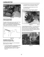
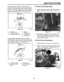
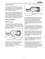
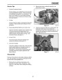
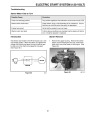
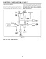
Switch leads are connected to the primary side of the
coil and to ground (see Figure 87). When the switch is
closed, the electronic ignition module is bypassed so
that it cannot interrupt primary current flow. This action
prevents the coil from producing the high voltage
necessary to generate spark. When the switch is
open, the ignition coil produces spark.
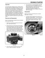
One of the ways the Lawn-Boy Corporation met these
requirements was with the “zone start system.” This
system utilizes a kill switch and a brake, which stops
the engine when the operator releases the blade
control bail (A). (See Figure 86.) The two-step blade
engagement criteria is met by requiring the operator to
pull the bail to the handle first, then pull the recoil rope
from the operator’s position.
Figure 87
0893-043
A
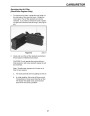
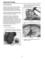
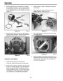
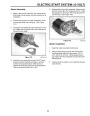
Stopping the engine and blade is accomplished by
means of a brake that is applied to the flywheel. The
brake spring is in the “braked” position when the blade
control is in the “at rest” or vertical position. When the
blade control bail is lowered to the mower handle, the
brake is retracted and allows the engine to run.
Figure 86
0893-048
47
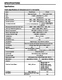
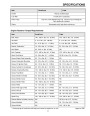
| Categories | Snow Blower Manuals, Toro Snow Blower |
|---|---|
| Tags | Toro 3650 GTS, Toro 38409, Toro 38412, Toro 38413, Toro 38414, Toro 38418, Toro 38419, Toro 38422, Toro 38424, Toro 38428, Toro 38429, Toro 38432, Toro 38433, Toro 38437, Toro 38438, Toro 38440, Toro 38441, Toro 38442, Toro 38445, Toro 38515, Toro 38516, Toro 38517, Toro 38518, Toro 38537, Toro 38538, Toro 38600, Toro 38601, Toro 38602, Toro 38603, Toro 38610, Toro 38611, Toro CCR 2400, Toro CCR 2400 GTS, Toro CCR 2450 GTS, Toro CCR 2500 GTS, Toro CCR 3000, Toro CCR 3000 GTS, Toro CCR 3650 GTS, Toro Power Max 6000, Toro Power Max 726TE, Toro Snow Commander |
| Model Number | 38412, 38418, 38413, 38419, 38422, 38424, 38440, 38428, 38429, 38432, 38433, 38437, 38438, 38439, 38440, 38441, 38442, 38445, 38515, 38537, 38538, 38600, 38601, 38602, 38603, 38610, 38611, 38419, 38516, 38517, 38518 |
| Model Year | 1999, 2000, 2001, 2002, 2004, 2005, 2007 |
| Download File |
|
| Document Type | Engine Service Manual |
| Language | English |
| Serial Number | 240000001 - 240999999 |
| Product Name | Toro Snow Commander Snowthrower |
| Product Brand | Toro. Customer Service Representatives are available by phone:
Monday - Friday 7:30 a.m. to 9:00 p.m. (CDT) - Saturday 8:00 a.m. to 8:00 p.m. (CDT) - Sunday 10:00 a.m. to 8:00 p.m. (CDT)
Canada 1-888-225-4886 USA 1-888-384-9939, Snow Blower |
| Product Type | Snowthrower |
| Product Series | Single Stage, Single Stage Snow Commander |
| Swath | 24 inch |
| Discharge | Single Stage |
| Engine Manufacturer | Toro |
| Engine Oil Type | Toro 2 cycle / NMMA-TCW3 |
| Engine Motor Model # | R-tek |
| Engine Motor Size | 7 hp |
| Engine Motor Type | 2 Cycle EPA2 |
| Document File Type | |
| Publisher | toro.com |
| Wikipedia's Page | Toro Company |
| Copyright | Attribution Non-commercial |
(0 votes, average: 0 out of 5)