


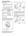


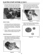
ELECTRIC START SYSTEM (12 VOLT)
Alternator Output Testing
Alternator Resistance Check
1.
To check output of the alternator accurately, it is
necessary to run the engine at operating speed,
± 300 RPM. Readjust the governor if
necessary. Refer to page 26 (Presetting the
Governor (DuraForce Engines Only).
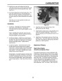
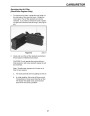
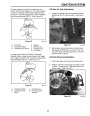
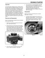
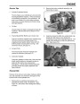
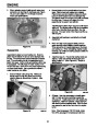
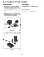
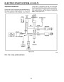
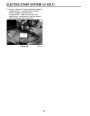
1. Disconnect the electronic cup assembly from the
wiring harness. Connect one ohmmeter (RX-1
scale) lead to the green wire of the wiring harness
and the other to the engine block. (See Figure
105.)
2900
2.
With the engine running, unplug the battery
connector and reconnect the plug so that only the
black wires are connected. Using a multimeter, set
to read 500 milliamps. Connect the red lead to the
red wire going to the battery and the black lead to
the red wire going to the mower.
2. Measure resistance. The resistance should be
from 2.7 to 3.3 ohms. If specification is not met,
check resistance at alternator connection. If
specification is met at the alternator, look at the
harness for breakage. If specification is not met at
alternator connection, replace the alternator.
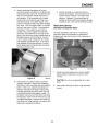
CAUTION: Keep hands and feet away from the
blade.
3.
Measure alternator output. The reading should be
from 190-450 M.A. (Milliampere) at 2900 ± 300
RPM. If output is not within specification, check
the alternator air gap.
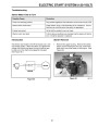
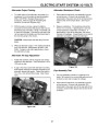
Alternator Air Gap Adjustment
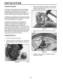
1.
Rotate the flywheel until the magnets are directly
adjacent to the alternator. There should be a .010”
(.25
mm) air gap.
Figure 105
0891-004
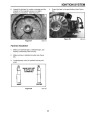
2.
If gap is incorrect, loosen the alternator mounting
bolts slightly allowing the flywheel magnets to pull
alternator against the gauge. Tighten the bolts to
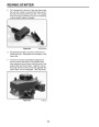
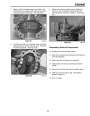
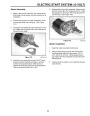
Cup Assembly Test
75
104.)
in. lbs., and recheck the air gap. (See Figure
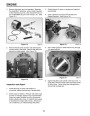
1.
The cup assembly consists of a capacitor and
diode. Its function is to convert alternating current
to direct current and increase the voltage.
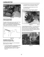
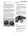
2.
Disconnect the electronic cup assembly from the
wiring harness. Connect one ohmmeter (RX-1
scale) lead to the green wire of the cup side of the
connector and the other lead to the red wire of the
connector.
Figure 104
6.tif
57
| Categories | Snow Blower Manuals, Toro Snow Blower |
|---|---|
| Tags | Toro 3650 GTS, Toro 38409, Toro 38412, Toro 38413, Toro 38414, Toro 38418, Toro 38419, Toro 38422, Toro 38424, Toro 38428, Toro 38429, Toro 38432, Toro 38433, Toro 38437, Toro 38438, Toro 38440, Toro 38441, Toro 38442, Toro 38445, Toro 38515, Toro 38516, Toro 38517, Toro 38518, Toro 38537, Toro 38538, Toro 38600, Toro 38601, Toro 38602, Toro 38603, Toro 38610, Toro 38611, Toro CCR 2400, Toro CCR 2400 GTS, Toro CCR 2450 GTS, Toro CCR 2500 GTS, Toro CCR 3000, Toro CCR 3000 GTS, Toro CCR 3650 GTS, Toro Power Max 6000, Toro Power Max 726TE, Toro Snow Commander |
| Model Number | 38412, 38418, 38413, 38419, 38422, 38424, 38440, 38428, 38429, 38432, 38433, 38437, 38438, 38439, 38440, 38441, 38442, 38445, 38515, 38537, 38538, 38600, 38601, 38602, 38603, 38610, 38611, 38419, 38516, 38517, 38518 |
| Model Year | 1999, 2000, 2001, 2002, 2004, 2005, 2007 |
| Download File |
|
| Document Type | Engine Service Manual |
| Language | English |
| Serial Number | 240000001 - 240999999 |
| Product Name | Toro Snow Commander Snowthrower |
| Product Brand | Toro. Customer Service Representatives are available by phone:
Monday - Friday 7:30 a.m. to 9:00 p.m. (CDT) - Saturday 8:00 a.m. to 8:00 p.m. (CDT) - Sunday 10:00 a.m. to 8:00 p.m. (CDT)
Canada 1-888-225-4886 USA 1-888-384-9939, Snow Blower |
| Product Type | Snowthrower |
| Product Series | Single Stage, Single Stage Snow Commander |
| Swath | 24 inch |
| Discharge | Single Stage |
| Engine Manufacturer | Toro |
| Engine Oil Type | Toro 2 cycle / NMMA-TCW3 |
| Engine Motor Model # | R-tek |
| Engine Motor Size | 7 hp |
| Engine Motor Type | 2 Cycle EPA2 |
| Document File Type | |
| Publisher | toro.com |
| Wikipedia's Page | Toro Company |
| Copyright | Attribution Non-commercial |
(0 votes, average: 0 out of 5)