


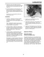
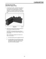
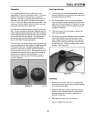

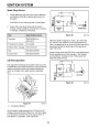
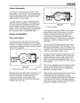
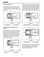


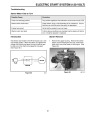
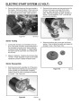
PIVOTING ZONE START BRAKE
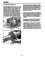
There are two versions of this brake. The function is
the same, but they contact different parts of the
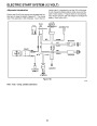
flywheel. Figure 88 is a diagram of the system used on
recoil start engines. The brake pad engages the
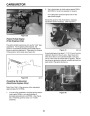
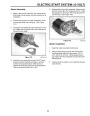
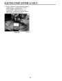
bottom of the flywheel. Figure 89 is a photo of a
slightly different system used on electric start engines.
On electric start engines, the brake pad must contact
the side of the flywheel to clear the teeth of the flywheel
ring gear.
Electric Start
Disassembly
Recoil
Figure 89
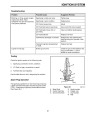
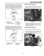
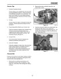
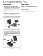
Note: Numbers in parentheses in the following
0893-040
procedures refer to the previous illustration (see Figure
88).
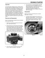
1.
If the engine and blade are taking more than 3
seconds to stop when the blade control bail is
released, inspect the brake pad for excessive wear
and replace if necessary. Note that the brake pad
and the brake plate are replaceable only as an
assembly.
Figure 88
3297-023
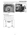
1
2
- Ground strap stop 6 - Plastic rivet
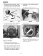
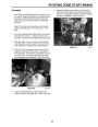
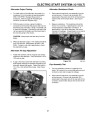
2. To reduce the pressure of the spring between
brake mounting plate (10) and brake plate (8),
squeeze tabs of brake cable that hold it in place at
the brake mounting plate. Push cable through the
hole in brake mounting plate.
(
self expanding) (2)
- Self-tapping
screw
7 - Shoulder screw
(10 mm)
3
- Brake switch lead
wire
8 - Brake plate assembly
9 - Screw
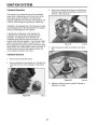
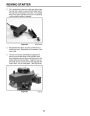
3. Slide cable out through horizontal slot in brake
mounting plate. Also, slide the ball end of the
cable up through the vertical slot in the brake plate.
4
5
- Ground strap
- Insulation strap
10 - Brake mounting plate
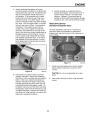
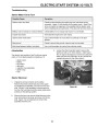
Note: In step 4, some units may use a 3/8" head
with 1/4" diameter screw (rather than a 10 mm).
4.
5.
Remove the 10 mm shoulder screw (7) to remove
the brake plate and brake pad attached to it.
If the ground strap or any part of this assembly
requires replacement, remove the second screw
(9)
to remove the brake mounting plate from the
engine.
48
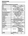
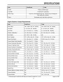
| Categories | Snow Blower Manuals, Toro Snow Blower |
|---|---|
| Tags | Toro 3650 GTS, Toro 38409, Toro 38412, Toro 38413, Toro 38414, Toro 38418, Toro 38419, Toro 38422, Toro 38424, Toro 38428, Toro 38429, Toro 38432, Toro 38433, Toro 38437, Toro 38438, Toro 38440, Toro 38441, Toro 38442, Toro 38445, Toro 38515, Toro 38516, Toro 38517, Toro 38518, Toro 38537, Toro 38538, Toro 38600, Toro 38601, Toro 38602, Toro 38603, Toro 38610, Toro 38611, Toro CCR 2400, Toro CCR 2400 GTS, Toro CCR 2450 GTS, Toro CCR 2500 GTS, Toro CCR 3000, Toro CCR 3000 GTS, Toro CCR 3650 GTS, Toro Power Max 6000, Toro Power Max 726TE, Toro Snow Commander |
| Model Number | 38412, 38418, 38413, 38419, 38422, 38424, 38440, 38428, 38429, 38432, 38433, 38437, 38438, 38439, 38440, 38441, 38442, 38445, 38515, 38537, 38538, 38600, 38601, 38602, 38603, 38610, 38611, 38419, 38516, 38517, 38518 |
| Model Year | 1999, 2000, 2001, 2002, 2004, 2005, 2007 |
| Download File |
|
| Document Type | Engine Service Manual |
| Language | English |
| Serial Number | 240000001 - 240999999 |
| Product Name | Toro Snow Commander Snowthrower |
| Product Brand | Toro. Customer Service Representatives are available by phone:
Monday - Friday 7:30 a.m. to 9:00 p.m. (CDT) - Saturday 8:00 a.m. to 8:00 p.m. (CDT) - Sunday 10:00 a.m. to 8:00 p.m. (CDT)
Canada 1-888-225-4886 USA 1-888-384-9939, Snow Blower |
| Product Type | Snowthrower |
| Product Series | Single Stage, Single Stage Snow Commander |
| Swath | 24 inch |
| Discharge | Single Stage |
| Engine Manufacturer | Toro |
| Engine Oil Type | Toro 2 cycle / NMMA-TCW3 |
| Engine Motor Model # | R-tek |
| Engine Motor Size | 7 hp |
| Engine Motor Type | 2 Cycle EPA2 |
| Document File Type | |
| Publisher | toro.com |
| Wikipedia's Page | Toro Company |
| Copyright | Attribution Non-commercial |
(0 votes, average: 0 out of 5)