
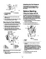


Installing the Auger/Impeller
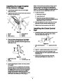
Drive Control Linkage
Note: If the force does not noticeably increase, remove
the belt cover (refer to Replacing the Auger/Impeller
Drive Belt, steps 1 and 2 on page 19) and measure two
inches (5.1 cm) above the handgrip at the point where you
remove the slack from the auger/impeller drive belt.
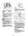
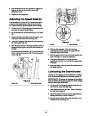
1.
Loosen the jam nut above the clevis on the upper
control rod (Fig. 8).
5.
To adjust the distance:
A. Remove the clevis pin.
B. Loosen the jam nut.
2.
Align the holes in the clevis and lower control rod and
insert the clevis pin (Fig. 8).
5
C. Thread the clevis up or down to increase or
decrease the distance between the handgrip and the
auger/impeller control lever (Fig. 8).
6.
7.
When the adjustment is correct, install the clevis pin
and secure it in place with the cotter pin (Fig. 8).
1
3
Tighten the jam nut to secure the clevis (Fig. 8).
2
Installing the Chute Control
Rod
4
6
649
Figure 8
1.
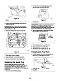
Assemble the chute control bracket and rod to the left
side of the handle with a capscrew and a locknut.
Leave the locknut loose (Fig. 10).
1.
2.
3.
Jam nut
4.
5.
6.
Lower control rod
Clevis pin
Clevis
Upper control rod
Cotter pin
2
3.
Check the distance between the top of the handgrip
and the bottom of the auger/impeller control lever
(Figs. 6 and 9). The distance should be approximately
four inches (10 cm).
1
886
Figure 10
1.
Chute control bracket and
rod
2.
Capscrew and locknut
1
3
4
2. Apply No. 2 general purpose grease to the worm gear.
3.
Loosely mount the worm gear and bracket to the
mounting flange with a bolt, a pyramidal washer, and a
locknut (Fig. 11).
665
2
4. Slide the worm gear into the teeth of the chute
retaining ring and tighten the locknut (Fig. 11).
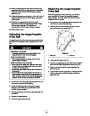
Figure 9
1.
2.
Auger/impeller control
lever
3.
4.
4 in. (10 cm)
1 to 2 in. (2.5 to 5.1 cm)
Handgrip
4.
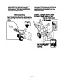
Press the auger/impeller control lever slowly toward
the handgrip.
The amount of force to compress the lever increases
noticeably when you remove the slack from the drive
belt (approximately one–half of the lever movement).
The adjustment is correct when the force begins to
increase and the distance between the top of the
handgrip and the bottom of the auger/impeller control
lever is one to two inches (2.5 to 5 cm) (Fig. 9).
9
| Categories | Snow Blower Manuals, Toro Snow Blower |
|---|---|
| Tags | Toro 38051, Toro 522 |
| Model Number | 38051 |
| Model Year | 2000 |
| Download File |
|
| Document Type | Operator's Manual |
| Language | English, Français |
| Serial Number | 000000001 - 000999999, 200000001 - 200999999 |
| Product Name | 522 Snowthrower |
| Product Brand | Toro. Customer Service Representatives are available by phone:
Monday - Friday 7:30 a.m. to 9:00 p.m. (CDT) - Saturday 8:00 a.m. to 8:00 p.m. (CDT) - Sunday 10:00 a.m. to 8:00 p.m. (CDT)
Canada 1-888-225-4886 USA 1-888-384-9939, Snow Blower |
| Product Type | Snowthrower |
| Product Series | Snowthrower, Two Stage Intermediate Frame |
| Swath | 22 inch |
| Discharge | Two Stage |
| Engine Manufacturer | Tecumseh |
| Engine Motor Model # | HSSK50-67401S |
| Engine Motor Size | 5 hp |
| Engine Motor Type | 4 Cycle CARB1, EPA1 |
| Transmission Speed | 3 Forward/1 Reverse |
| Transmission Type | Friction Disc |
| Document File Type | |
| Publisher | toro.com |
| Wikipedia's Page | Toro Company |
| Copyright | Attribution Non-commercial |
(0 votes, average: 0 out of 5)