


7.
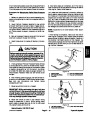
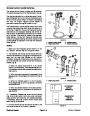
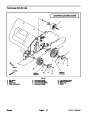
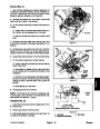
Rotate brush a few times and center brush in frame.
Raise Processor so that brush is slightly off ground.
1
FRONT
8.
Secure brush shaft in bearings (see Flange Bearing
Service in this section).
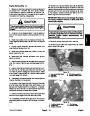
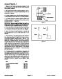
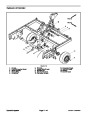
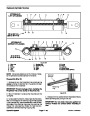
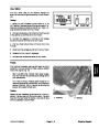
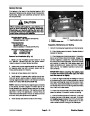
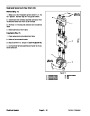
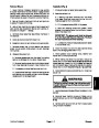
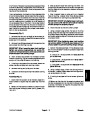
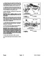
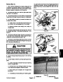
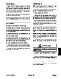
NOTE: Chopper tip orientation
in relation to brush housing
9.
Rotate chopper axle so that a row of chopper tips is
aligned with the brush housing corner. Rotate brush
shaft so that one of the brush tips is aligned with the ro-
tating corner shaft (Fig. 30).
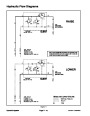
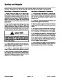
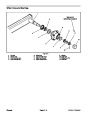
IMPORTANT: When installing pulleys and drive
belts, make sure to properly align drive, driven and
idler pulleys.
3
NOTE: When installing pulley on right end of brush
shaft, align pulley and drive belt with drive pulley on
chopper axle.
2
CHOPPER AXLE TO
BRUSH ORIENTATION
NOTE: Brush orientation
in relation to rotating
corner shaft
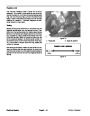
IMPORTANT: Make sure that brush shaft and chop-
per axle are properly aligned as drive belt is
installed on right end of brush shaft (Fig. 30). Im-
proper alignment will decrease machine perfor-
mance and may lead to increased debris buildup in
Processor that can cause accelerated component
wear and damage.
Figure 30
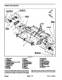
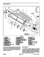
1.
2.
Chopper axle
Brush shaft
3.
Rotating corner shaft
3
1
2
10.Install
square key, pulley, taper lock bushing and
drive belt to right end of brush shaft (see Pulley Assem-
bly Service in this section).
NOTE: Wheninstalling pulley onleftendofbrushshaft,
align pulley and drive belt with driven pulley on rotating
corner shaft.
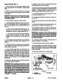
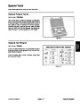
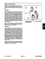
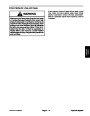
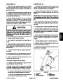
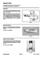
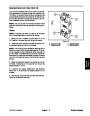
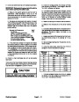
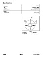
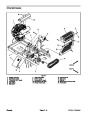
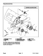
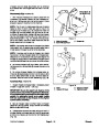
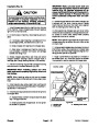
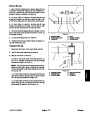
0.050”
(1.3 mm)
UP
11.
Install square key, pulley, taper lock bushing and
Idler Face to Sheave Face
drive belt to left end of brush shaft (see Pulley Assembly
Service in this section).
Figure 31
3. Idler pulley
1.
2.
Brush shaft
Chopper axle
12.Adjust
drive belt idler pulleys to achieve proper ten-
sion on drive belts (see Operator’s Manual). After ad-
justment, make sure that chopper axle and brush shaft
are still properly aligned (Fig. 30).
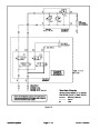
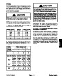
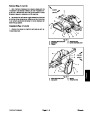
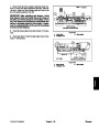
IMPORTANT: After adjusting belt tension, check
that distance from idler pulley face to the faces of
the drive and driven pulleys is correct (Figs. 31 and
1
3
2
32).
This distance is necessary to ensure that idler
pulley is correctly aligned to drive belts. If neces-
sary, re--adjust positions of drive and driven pulleys
to allow correct distance.
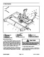
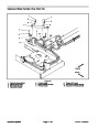
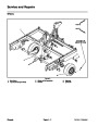
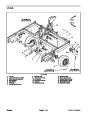
13.Secure
side shield (item 8), angle plate (item 7) and
side skirt plate (item 9) to each side of machine with two
flange nuts and carriage screws.
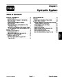
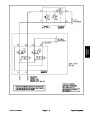
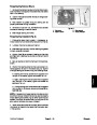
Idler Face and Sheave Faces
in Alignment
UP
(2)
Figure 32
14.Install
tion).
belt covers (see Drive Belt Covers in this sec-
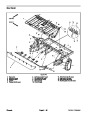
1.
2.
Brush shaft
3. Idler pulley
Rotating corner shaft
Chassis
Page 6 -- 26
ProCore Processor
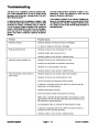
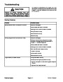
| Categories | Lawn Mower Manual, Sprinkler and Irrigation Manuals, Toro Sprinkler and Irrigation Manuals |
|---|---|
| Download File |
|
| Document Type | Catalog |
| Language | English |
| Product Brand | Toro. Customer Service Representatives are available by phone:
Monday - Friday 7:30 a.m. to 9:00 p.m. (CDT) - Saturday 8:00 a.m. to 8:00 p.m. (CDT) - Sunday 10:00 a.m. to 8:00 p.m. (CDT)
Canada 1-888-225-4886 USA 1-888-384-9939, Lawn Mower |
| Document File Type | |
| Publisher | toro.com |
| Wikipedia's Page | Toro Company |
| Copyright | Attribution Non-commercial |
(0 votes, average: 0 out of 5)