


4.
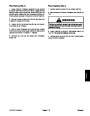
Loosen straps that secure fuel tank to machine
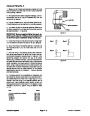
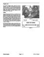
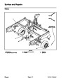
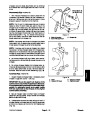
6. Align upper lift cylinder clevis to frame. Secure cylin-
der clevis with shoulder bolt and pivot pin.
frame(seeFuelTankRemovalinthissection).Shifttank
position toward right side of machine to allow access to
upper lift cylinder pivot pin.
7.
Position fuel tank correctly on frame and secure tank
to machine frame (see Fuel Tank Removal in this sec-
tion).
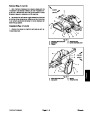
5.
Remove shoulder bolt and pivot pin that secure up-
per clevis of lift cylinder to frame. Rotate top of lift cylin-
der to allow access to centrifugal clutch.
8.
Install muffler guard, belt guard and belt cover (see
Drive Belt Covers in the Service and Repairs section of
Chapter 6 -- Chassis). Make sure that fuel line is not
pinched between belt guard and machine frame.
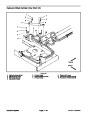
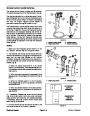
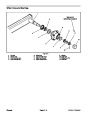
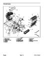
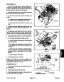
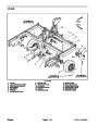
6.
Remove cap screw (item 18) and flat washer (item
that secure clutch to engine crankshaft.
17)
7.
from centrifugal clutch pulley.
Loosen drive belt tension and remove drive belts
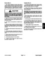
9. Connect cables to battery terminals. Connect posi-
tive battery cable first and then negative cable.
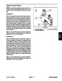
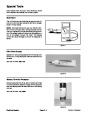
IMPORTANT: To protect the engine crankshaft dur-
ing clutch removal, place thick washer on end of
crankshaft and lightly grease end of clutch puller.
10.Install spark plug wires to spark plugs.
2
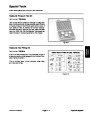
8.
puller (see Special Tools in this Chapter).
Remove clutch from engine crankshaft with clutch
1
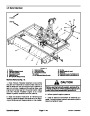
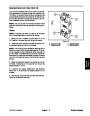
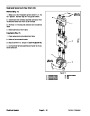
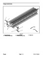
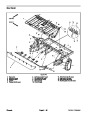
Installation (Fig. 8)
1.
Thoroughly clean tapers on engine crankshaft and
centrifugal clutch bore.
2.
3.
andflatwasher.Torquecapscrewfrom270to330in--lb
(31
Slide centrifugal clutch onto engine crankshaft.
Secure clutch to engine crankshaft with cap screw
3
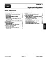
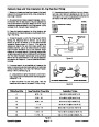
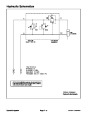
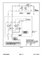
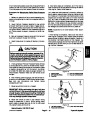
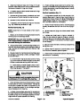
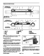
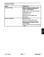
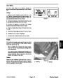
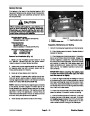
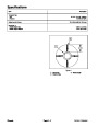
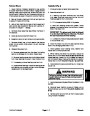
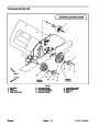
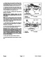
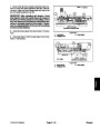
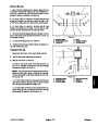
0.330”
Idler Face to Sheave Face
(8.4 mm)
FRONT
to 37 N--m).
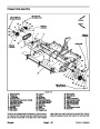
Figure 9
3.
4.
pulley.
Install drive belts to centrifugal clutch and jack shaft
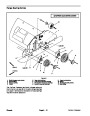
1.
2.
Jack shaft
Centrifugal clutch
Idler pulley
5.
sion on drive belts (see Operator’s Manual).
Adjust drive belt idler pulley to achieve proper ten-
3
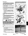
IMPORTANT: After adjusting belt tension, check
that distance from idler pulley face to the faces of
the clutch drive pulley and jack shaft driven pulley
is correct (Fig. 9). This distance is necessary to en-
sure that idler pulley is correctly aligned to drive
belts. If necessary, either adjust position of engine
on machine frame or the driven pulley on jack shaft
(see Jack Shaft Assembly in the Service and Re-
pairs section of Chapter 6 -- Chassis) to allow cor-
rect distance.
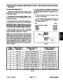
2
1
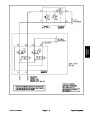
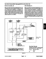
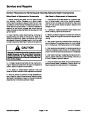
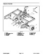
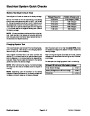
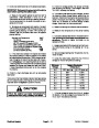
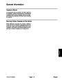
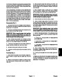
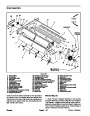
IMPORTANT: When securing lift cylinder pivot pin
to frame, there should be clearance between the
shoulderboltheadandpivotpin.Donotovertighten
shoulder bolt.
Figure 10
1.
2.
Lift cylinder
Pivot pin
3.
Shoulder bolt
ProCore Processor
Page 3 -- 11
Engine
| Categories | Lawn Mower Manual, Sprinkler and Irrigation Manuals, Toro Sprinkler and Irrigation Manuals |
|---|---|
| Download File |
|
| Document Type | Catalog |
| Language | English |
| Product Brand | Toro. Customer Service Representatives are available by phone:
Monday - Friday 7:30 a.m. to 9:00 p.m. (CDT) - Saturday 8:00 a.m. to 8:00 p.m. (CDT) - Sunday 10:00 a.m. to 8:00 p.m. (CDT)
Canada 1-888-225-4886 USA 1-888-384-9939, Lawn Mower |
| Document File Type | |
| Publisher | toro.com |
| Wikipedia's Page | Toro Company |
| Copyright | Attribution Non-commercial |
(0 votes, average: 0 out of 5)