


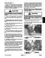


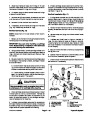


5.
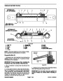
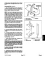
Mount rod securely in a vise by clamping vise on the
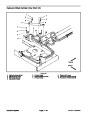
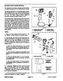
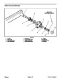
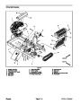
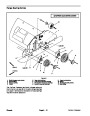
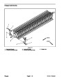
3. Install O--rings (items 3 and 12), seal (item 2) and
wear ring (item 1) to piston.
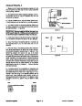
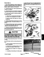
flatsofthepivot.Removelocknut(item14)andcarefully
slidepistonandheadfromtherod.Onoffsetcylinder,re-
move spacer (item 16) from rod.
IMPORTANT: Do not clamp vise jaws against rod
surface. Protect rod surface before mounting in
vise.
IMPORTANT: When removing seal components, be
careful not to scratch or damage piston or head.
4.
Mount rod securely in a vise by clamping vise on the
6.
and O--rings (items 3 and 12) from piston.
Remove and discard wear ring (item 1), seal (item 2)
pivot end of the shaft. On offset cylinder, slide spacer
(item 16) onto rod. Carefully slide head assembly and
piston assembly onto the rod.
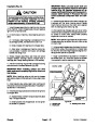
7.
Remove and discard O--ring (item 6), backup ring
(item 7), wiper (item 10) and seal (item 11) from the
head.
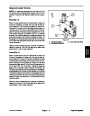
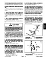
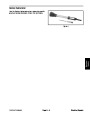
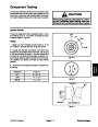
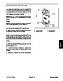
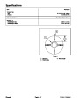
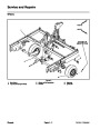
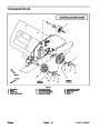
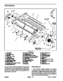
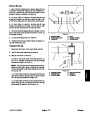
5. Thread lock nut (item 14) onto rod. Torque lock nut
to value shown in Figure 22.
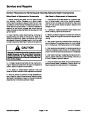
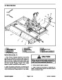
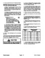
Inspection
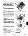
6. Remove rod assembly from vise.
IMPORTANT: Prevent damage when clamping the
tube into a vise; clamp on the pivot end only.
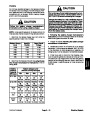
CAUTION
7.
Mount tube in a vise so that the rod end tilts up slight-
Use eye protection such as goggles when using
compressed air
ly.
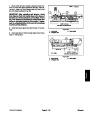
IMPORTANT: When installing the head into the
tube, pay careful attention to the retaining ring slot
in the tube to insure that the backup ring does not
lodge in the slot.
1.
air.
Wash all parts in solvent. Dry parts with compressed
2.
out--of--roundness and bending. Replace if worn or
damaged.
Inspect internal surface of tube for deep scratches,
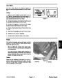
8.
ofclean hydraulic oil.Sliderod assembly into tubebeing
careful not to damage the seals.
Coat all internal lift cylinder parts with a light coating
3.
scoring or wear. Replace any worn or damaged parts.
Inspect rod, piston and head for excessive pitting,
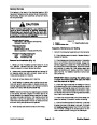
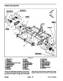
9.
8):
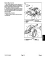
Secure head in tube by installing retaining ring (item
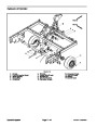
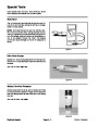
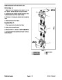
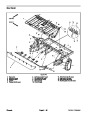
Assembly (Fig. 22)
A. Align retaining ring hole in the head with the ac-
cess slot in the tube.
1.
Coat new backup ring, wiper, seals and O--rings with
clean hydraulic oil.
B. Insert the retaining ring hook into the hole and ro-
tate head clockwise until the retaining ring is com-
pletely pulledintothetubeandtheendsarecovered.
IMPORTANT: When installing seal components, be
careful not to scratch or damage piston or head.
C. Fill retaining ring slot in cylinder tube with silicone
sealant after retaining ring is installed.
2.
(item 11) and wiper (item 10) to the head.
Install backup ring (item 7), O--ring (item 6), seal
ProCore Processor
Page 4 -- 29
Hydraulic System
| Categories | Lawn Mower Manual, Sprinkler and Irrigation Manuals, Toro Sprinkler and Irrigation Manuals |
|---|---|
| Download File |
|
| Document Type | Catalog |
| Language | English |
| Product Brand | Toro. Customer Service Representatives are available by phone:
Monday - Friday 7:30 a.m. to 9:00 p.m. (CDT) - Saturday 8:00 a.m. to 8:00 p.m. (CDT) - Sunday 10:00 a.m. to 8:00 p.m. (CDT)
Canada 1-888-225-4886 USA 1-888-384-9939, Lawn Mower |
| Document File Type | |
| Publisher | toro.com |
| Wikipedia's Page | Toro Company |
| Copyright | Attribution Non-commercial |
(0 votes, average: 0 out of 5)