


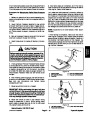
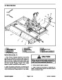


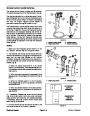
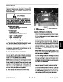
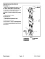


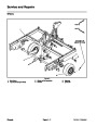
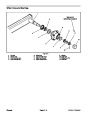
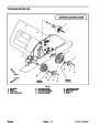

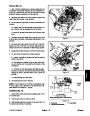

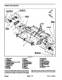


Installation (Fig. 19)
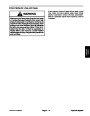
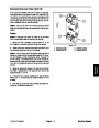
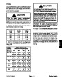
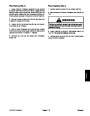
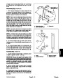
IMPORTANT: Make sure that brush shaft and
chopper axle are properly aligned as drive belt is
installed (Fig. 23). Improper alignment will de-
crease machine performance and may lead to in-
creased debris buildup in Processor that can
cause accelerated component wear and dam-
age.
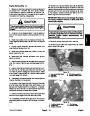
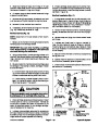
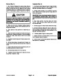
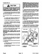
CAUTION
To prevent personal injury, make sure that chop-
per assembly is properly supported as it is
installed to the machine. Chopper assembly
weighs approximately 125 pounds (57 kg).
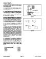
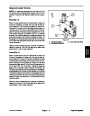
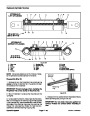
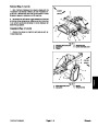
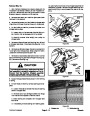
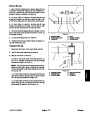
C. Rotate chopper axle so that a row of chopper tips
is aligned with the brush housing corner. Rotate
brush shaft so that one of the brush tips is aligned
with the rotating corner shaft (Fig. 23).
1.
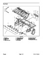
Install chopper assembly into machine from the rear
of the machine. Clean chopper axle ends and apply a
light film of oil to shaft ends.
D. After positioning chopper axle and brush shaft,
installdrivebelttosprocketonchopperaxleanddriv-
en pulley on brush shaft. Keep shafts properly
aligned as drive belt is installed.
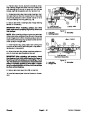
2.
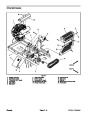
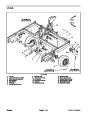
On both sides of machine, install bearing and end-
plate:
NOTE: Whenpositioningpulleyontotherightendof
chopper axle, align pulley and belt with driven pulley
on brush shaft.
A. If removed, attach bearing to endplate with four
(4) carriage screws, flat washers and lock nuts.
B. Slide endplate with bearing onto chopper axle.
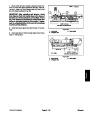
E. Using astraightedgeacrossthefaceofthebrush
shaft driven pulley, move sprocket on chopper axle
so that drive belt and straight edge are aligned indi-
cating correct position of sprocket.
C. Align holes in endplate and machine frame. Se-
cure endplate in position with seven (7) carriage
screws and flange nuts.
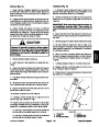
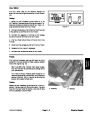
3.
chopper between bearings. Secure chopper axle in
bearings (see Flange Bearing Service in this section).
Rotate chopper assembly a few times and center
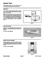
F. Apply Loctite #242 (or equivalent) to threads of
set screws (item 15). Install and tighten set screws
into sprocket to secure sprocket to chopper axle.
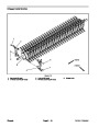
4.
and secure with removed fasteners (Fig. 22).
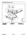
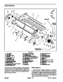
Position reinforcing ring (item 8) to chopper housing
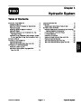
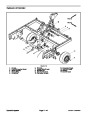
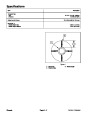
FRONT
1
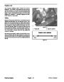
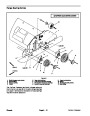
IMPORTANT: When installing pulleys and drive
belts, make sure to properly align drive, driven and
idler pulleys.
NOTE: Chopper tip orientation
in relation to brush housing
NOTE: When installing pulley on left end of chopper
axle,alignpulley anddrivebelts with drivepulley onjack
shaft.
5.
drivebeltstoleftendofchopperaxle(seePulleyAssem-
bly Service in this section).
Install square key, pulley, taper lock bushing and
3
6.
of chopper axle:
Installsquarekey,sprocketanddrivebelttorightend
2
A. Apply antiseize lubricant to square key and place
key in chopper axle slot.
CHOPPER AXLE TO
BRUSH ORIENTATION
NOTE: Brush orientation
in relation to rotating
corner shaft
Figure 23
B. Slide sprocket onto chopper axle. Do not tighten
set screws in sprocket.
1.
2.
Chopper axle
Brush shaft
3.
Rotating corner shaft
Chassis
Page 6 -- 22
ProCore Processor
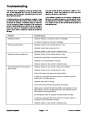
| Categories | Lawn Mower Manual, Sprinkler and Irrigation Manuals, Toro Sprinkler and Irrigation Manuals |
|---|---|
| Download File |
|
| Document Type | Catalog |
| Language | English |
| Product Brand | Toro. Customer Service Representatives are available by phone:
Monday - Friday 7:30 a.m. to 9:00 p.m. (CDT) - Saturday 8:00 a.m. to 8:00 p.m. (CDT) - Sunday 10:00 a.m. to 8:00 p.m. (CDT)
Canada 1-888-225-4886 USA 1-888-384-9939, Lawn Mower |
| Document File Type | |
| Publisher | toro.com |
| Wikipedia's Page | Toro Company |
| Copyright | Attribution Non-commercial |
(0 votes, average: 0 out of 5)