


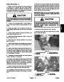
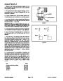
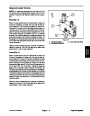


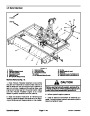


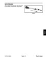
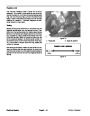
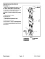
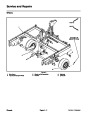
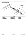
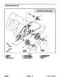
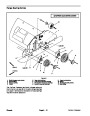


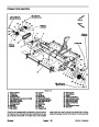
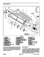


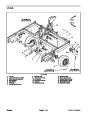
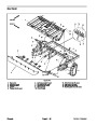


Removal (Fig. 38)
Have ProCore Processor attached to tow vehicle
andparkmachinesonalevelsurfacewiththeProcessor
fully lowered. Engage vehicle parking brake, stop en-
gineandremovekeyfromtheignitionswitch. Makesure
that Processor engine is off. Chock wheels to prevent
movement of either machine.
Installation (Fig. 38)
1.
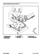
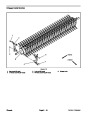
1. Ifadjustmentplatesandadjusterkeyswereremoved
from frame, secure them to frame with carriage screws,
flat washers and flange nuts to location noted during re-
moval.
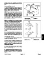
2.
to shaft ends. Place bearing onto each end of roller
shaft. Do not install bearing set screws at his time.
Clean roller shaft ends and apply antiseize lubricant
2.
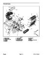
Loosen flange nuts and carriage screws that secure
roller scraper to brush housing. Position roller scraper
away from roller.
3.
4.
Position roller assembly under raised machine.
SlowlylowerProCoreProcessortocorrectlyposition
roller assembly to frame.
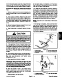
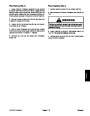
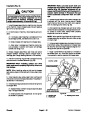
CAUTION
5.
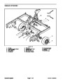
Align mounting holes in bearings and frame. Secure
bearings to frame with carriage screws (item 17), flat
washers (item 16) and lock nuts (item 15).
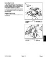
To prevent personal injury, make sure that roller
is supported as it is removed from the machine.
Roller weighs approximately 110 pounds (49 kg).
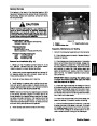
6.
Raise Processor so that roller is slightly off ground.
7.
bearings.
Rotate roller a few times and center roller between
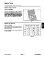
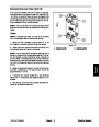
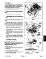
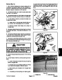
3.
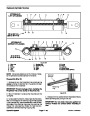
4.
each flange mount bearing locking collar to roller shaft.
Using the blind hole in bearing collar as a striking point,
unlock collar from roller shaft by rotating the collar with
a punch in the opposite direction of normal roller rota-
tion.
Support roller to prevent it from shifting.
Loosen and remove set screw (item 9) that secures
8.
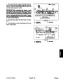
Using the blind hole in flange mount bearing locking
collars as a striking point, lock collars to roller shaft by
rotating the collars with a punch in the direction of nor-
mal roller rotation.
9.
Apply Loctite #242 (orequivalent) tothreads ofbear-
ing set screws (item 9). Install set screws into bearing
housings to secure bearings to roller shaft.
5.
screws (item 17), flat washers (item 16) and lock nuts
(item 15) that secure bearing to adjuster plate.
On each side of machine, remove two (2) carriage
10.Check
exists.
that roller is free to rotate and that no binding
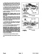
6.
Slowly raise Processor while allowing roller to re-
main on the ground. Support Processor to prevent it
from lowering.
11.
mm) between scraper and roller. Secure roller scraper
with carriage screws and flange nuts.
Adjust position of roller scraper to allow 0.060” (1.5
7.
8.
9.
Remove roller from machine.
12.Check
just if necessary (see Operator’s Manual).
roller height and roller scraper clearance. Ad-
Slide bearings from roller shaft.
If necessary, remove roller adjuster plates and ad-
juster keys from frame:
A. Note location of adjustment plates and adjuster
keys for assembly purposes.
B. Remove flange nuts, flat washers and carriage
screws that secure roller adjustment plates and ad-
juster keys to frame.
ProCore Processor
Page 6 -- 33
Chassis
| Categories | Lawn Mower Manual, Sprinkler and Irrigation Manuals, Toro Sprinkler and Irrigation Manuals |
|---|---|
| Download File |
|
| Document Type | Catalog |
| Language | English |
| Product Brand | Toro. Customer Service Representatives are available by phone:
Monday - Friday 7:30 a.m. to 9:00 p.m. (CDT) - Saturday 8:00 a.m. to 8:00 p.m. (CDT) - Sunday 10:00 a.m. to 8:00 p.m. (CDT)
Canada 1-888-225-4886 USA 1-888-384-9939, Lawn Mower |
| Document File Type | |
| Publisher | toro.com |
| Wikipedia's Page | Toro Company |
| Copyright | Attribution Non-commercial |
(0 votes, average: 0 out of 5)