


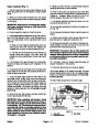
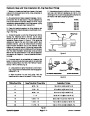
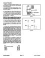
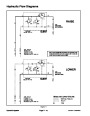
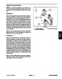
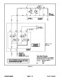
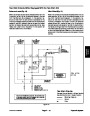


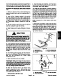
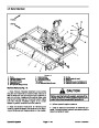
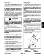
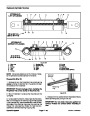


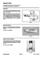
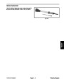
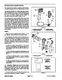
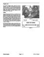
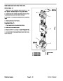
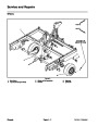
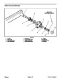
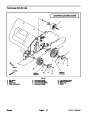

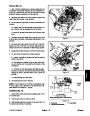
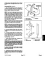
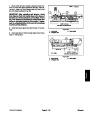


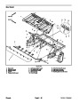


Removal (Fig. 39)
Have ProCore Processor attached to tow vehicle
andparkmachinesonalevelsurfacewiththeProcessor
fully lowered. Engage vehicle parking brake, stop en-
gineandremovekeyfromtheignitionswitch. Makesure
that ProCore Processor engine is off. Chock wheels to
prevent movement of either machine.
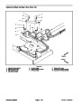
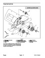
Installation (Fig. 39)
1.
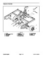
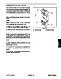
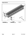
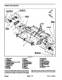
NOTE: Bearing tubes should be installed on lift axle
with bracket flange toward end of lift axle tube.
1.
ing tube to lift axle with hitch pin and lynch pin.
Slide bearing tubes onto lift axle. Secure each bear-
2.
3.
machine frame. Install cap screws (item 15), flat wash-
ers (item 10) and lock nuts (item 12) to frame and bear-
ing tubes. Do not fully tighten fasteners at this time.
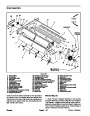
Position lift axle under machine.
2.
Secure lift axle to frame with hitch pin and lynch pin
Raise lift axle and align bearing tubes (item 17) to
to prevent lift axle from shifting.
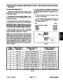
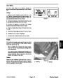
3.
jack stands (see Operator’s Manual and Jacking In-
structions in Chapter 1 -- Safety).
Jack or hoist machine from ground and support with
4.
Align axle blocks (item 9) toliftaxleand frame.Install
cap screws (item 11), flat washers (item 10) and lock
nuts(item12)toframeandaxleblocks.Donotfullytight-
en fasteners at this time.
4.
al in this section).
Removebothwheelassemblies(seeWheelRemov-
5.
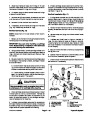
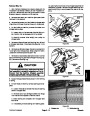
6.
that secures pivot pin to lift cylinder. Slide pivot pin from
liftcylinderandliftaxlebracket.Separateliftcylindercle-
vis from axle bracket.
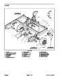
Support lift axle to prevent it from shifting.
5.
Center lift axle in axle blocks and bearing tubes.
At lower clevis of lift cylinder, remove shoulder bolt
Tighten fasteners that secure bearing tubes (item 17)
first and then tighten fasteners that secure axle blocks
(item 9). Torque fasteners from 67 to 83 ft--lb (91 to 112
N--m).
7.
and cap screws (item 15) that secure bearing tubes
(item 17) to machine frame.
Remove lock nuts (item 12), flat washers (item 10)
IMPORTANT: When securing lift cylinder pivot pin
to frame, do not overtighten shoulder bolt. There
should be clearance between the shoulder bolt
head and pivot pin.
8.
Remove lock nuts (item 12), flat washers (item 10)
and cap screws (item 11) that secure axle blocks (item
6. Install pivot pin tolower liftcylinder clevis and liftaxle
bracket. Secure pivot pin to lift cylinder with shoulder
bolt.
9)
9.
to machine frame. Remove axle bearings.
Lower lift axle and remove from the machine.
10.Remove
bearingtubetoliftaxle.Slidebearingtubesfromliftaxle.
lynch pin and hitch pin that secures each
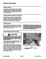
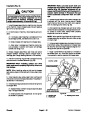
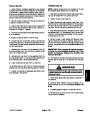
WARNING
Failure to maintain proper lug nut torque could
resultinfailureorloss ofwheelandmayresultin
personal injury.
11.
and Bearings in this section.
If wheel hub service is necessary, see Wheel Hubs
7.
Install wheel assemblies (see Wheel Installation in
this section).
8.
properly torque lug nuts from 70 to 90 ft--lb (95 to 122
N--m).
Carefully lower machine to ground. Make sure to
9.
Lubricate grease fittings on lift axle pivot points.
lynch pin and hitch pin from lift axle before
10.Remove
using ProCore Processor.
ProCore Processor
Page 6 -- 35
Chassis
| Categories | Lawn Mower Manual, Sprinkler and Irrigation Manuals, Toro Sprinkler and Irrigation Manuals |
|---|---|
| Download File |
|
| Document Type | Catalog |
| Language | English |
| Product Brand | Toro. Customer Service Representatives are available by phone:
Monday - Friday 7:30 a.m. to 9:00 p.m. (CDT) - Saturday 8:00 a.m. to 8:00 p.m. (CDT) - Sunday 10:00 a.m. to 8:00 p.m. (CDT)
Canada 1-888-225-4886 USA 1-888-384-9939, Lawn Mower |
| Document File Type | |
| Publisher | toro.com |
| Wikipedia's Page | Toro Company |
| Copyright | Attribution Non-commercial |
(0 votes, average: 0 out of 5)