


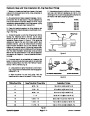
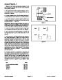
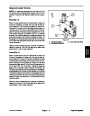


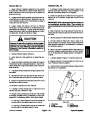


5.
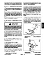
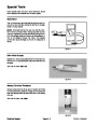
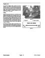
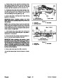
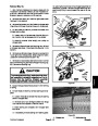
Support corner shaft tokeep itfrom shifting orfalling.
NOTE: Corner shaft rotates counterclockwise as
viewed from right side of machine.
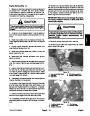
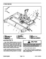
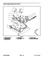
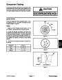
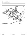
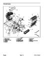
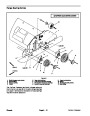
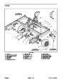
CHOPPER
AXLE
RIGHT
FRONT
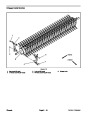
6.
Loosen set screw that secures both flange mount
bearinglockingcollarstorotatingcornershaft.Usingthe
blindholeinbearing collar asastriking point, unlock col-
lars from corner shaft by rotating the collar in the oppo-
site direction of shaft rotation with a punch.
7.
secure flange bearings to machine frame. Slide flange
bearings from corner shaft.
Removetwo(2)flangenuts andcarriage screwsthat
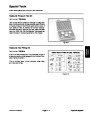
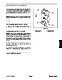
BRUSH
SHAFT
8.
Remove rotating corner shaft from machine.
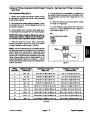
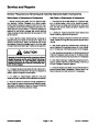
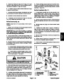
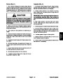
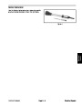
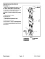
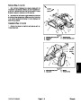
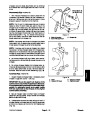
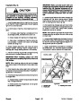
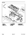
Installation (Fig. 33)
Clean both ends of rotating corner shaft and apply
ROTATING
CORNER
SHAFT
JACK
SHAFT
Figure 34
1.
antiseize lubricant to shaft ends. Install rotating corner
shaft into frame holes.
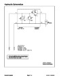
RIGHT
FRONT
2
2.
shaft.
Slideflangemountbearingsontobothendsofcorner
3.
riage screws, flat washers and flange nuts.
Secure both bearings to machine with two (2) car-
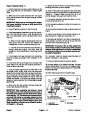
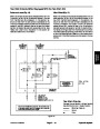
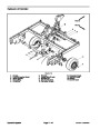
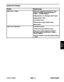
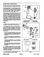
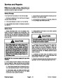
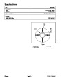
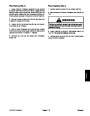
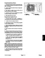
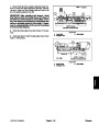
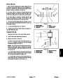
4.
inbearings sorightendofshaftis1.960”(49.8mm)from
side of machine frame (Fig. 35).
Rotatecornershaftafewtimes.Positioncornershaft
1
NOTE: Corner shaft rotates counterclockwise as
viewed from right side of machine.
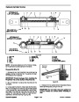
5.
Using the blind hole in flange mount bearing locking
collars as a striking point, lock collars to corner shaft by
rotatingthecollars withapunchinthedirection ofcorner
shaft rotation. Tighten set screw to secure each bearing
locking collar to corner shaft.
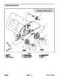
1.960”
(49.8 mm)
Figure 35
1.
Rotating corner shaft
2. Brush shaft
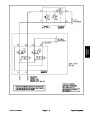
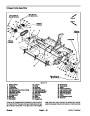
6.
Applyantiseizelubricanttosquarekeyandplacekey
into corner shaft slot.
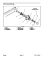
IMPORTANT: When installing pulley and drive belt,
make sure to properly align drive, driven and idler
pulleys.
1
3
2
NOTE: When installing pulley on rotating corner shaft,
align pulley and drive belt with drive pulley on brush
shaft.
7.
Slide pulley onto corner shaft with pulley flange to-
ward end of shaft.
IMPORTANT: DO NOT tighten pulley set screws un-
til after the drive belt is installed and the pulleys are
properly aligned.
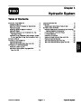
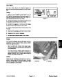
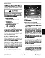
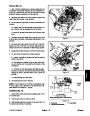
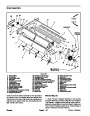
Idler Face and Sheave Faces
in Alignment
UP
Figure 36
8.
Install drive belt to drive and driven pulleys.
1.
2.
Brush shaft
Rotating corner shaft
3.
Idler pulley
ProCore Processor
Page 6 -- 29
Chassis
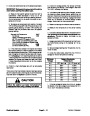
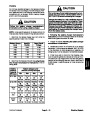
| Categories | Lawn Mower Manual, Sprinkler and Irrigation Manuals, Toro Sprinkler and Irrigation Manuals |
|---|---|
| Download File |
|
| Document Type | Catalog |
| Language | English |
| Product Brand | Toro. Customer Service Representatives are available by phone:
Monday - Friday 7:30 a.m. to 9:00 p.m. (CDT) - Saturday 8:00 a.m. to 8:00 p.m. (CDT) - Sunday 10:00 a.m. to 8:00 p.m. (CDT)
Canada 1-888-225-4886 USA 1-888-384-9939, Lawn Mower |
| Document File Type | |
| Publisher | toro.com |
| Wikipedia's Page | Toro Company |
| Copyright | Attribution Non-commercial |
(0 votes, average: 0 out of 5)