


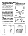
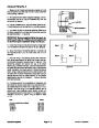
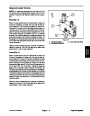


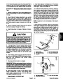
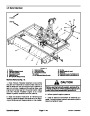
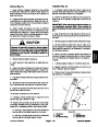


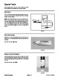
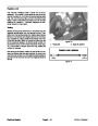
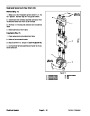
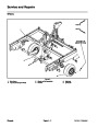
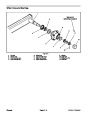
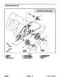

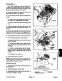

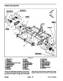
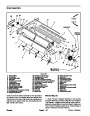


Remote Control Handle Switches
The remote control handle includes two (2) switches:
the engine stop switch and the lift/offset switch (Fig. 8).
3
E
D
The engine stop switch is a momentary switch that al-
lows the operator to shut the ProCore Processor engine
off from the tow vehicle. When this switch is depressed
and held, the engine magneto ignition system is
grounded to cause the engine to stop running.
2
C
1
B
A
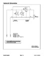
The lift/offset switch is a two position switch that is used
to control the optional tow hitch. When this switch is in
the normal, lift position, the tow hitch hydraulic manifold
solenoids are not energized allowing tow vehicle hy-
draulic flow to be available for operation of the Proces-
sor lift cylinder. If the switch is moved to the alternate,
offset position, the tow hitch hydraulic manifold sole-
noids are energized allowing tow vehicle hydraulic flow
to be available for operation of the tow hitch hydraulic
offset cylinder.
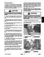
4
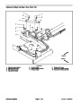
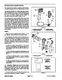
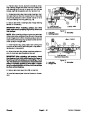
Figure 8
1.
2.
Remote control handle
Engine stop switch
3.
4.
Lift/offset switch
Harness connector
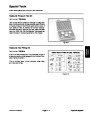
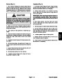
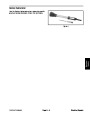
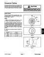
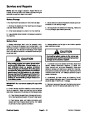
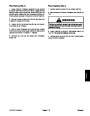
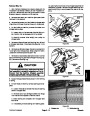
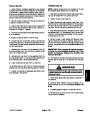
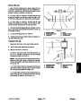
Testing
2
1.
Make sure that Processor ignition switch is in the
OFF position. Remove key from the ignition switch.
2.
The switches and remote control handle wire har-
nesscanbecheckedbyunpluggingthehandlewirehar-
ness from the main wire harness of the ProCore
Processor.Using aMultimeter set toohms, testcontinu-
ity of the switches and remote handle wire harness as
follows (Fig. 8):
1
A. When the engine stop switch is in the normal
position (not depressed), there should not be conti-
nuity between handle wire harness connector termi-
nals B and E.
B. When the engine stop switch is depressed, there
shouldbecontinuity betweenconnector terminalsB
and E.
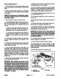
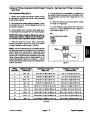
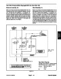
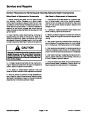
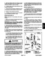
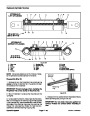
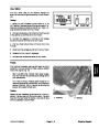
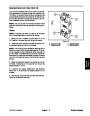
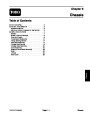
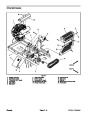
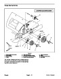
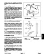
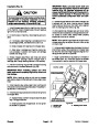
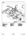
Figure 9
C. When the lift/offset switch is in the lift position,
there should not be continuity between connector
terminals A and C.
1.
Engine stop switch
2.
Lift/offset switch
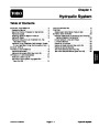
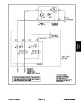
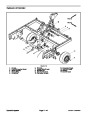
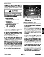
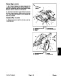
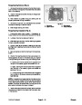
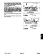
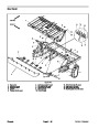
1
1A
LIFT/OFFSET
D. When the lift/offset switch is in the offset position,
thereshouldbecontinuitybetweenconnectortermi-
nals A and C.
SWITCH
TERMINALS
3.
If necessary, disassemble remote control handle
(Fig. 9) and test switch continuity using information
above at switch terminals (Fig. 10). Replace switch(es)
if necessary. Assemble remote control handle after
switch testing is completed.
ENGINE STOP
SWITCH
1
TERMINALS
1A
4.
main wire harness of the ProCore Processor.
Connect remote control handle wire harness to the
Figure 10
Electrical System
Page 5 -- 8
ProCore Processor
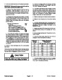
| Categories | Lawn Mower Manual, Sprinkler and Irrigation Manuals, Toro Sprinkler and Irrigation Manuals |
|---|---|
| Download File |
|
| Document Type | Catalog |
| Language | English |
| Product Brand | Toro. Customer Service Representatives are available by phone:
Monday - Friday 7:30 a.m. to 9:00 p.m. (CDT) - Saturday 8:00 a.m. to 8:00 p.m. (CDT) - Sunday 10:00 a.m. to 8:00 p.m. (CDT)
Canada 1-888-225-4886 USA 1-888-384-9939, Lawn Mower |
| Document File Type | |
| Publisher | toro.com |
| Wikipedia's Page | Toro Company |
| Copyright | Attribution Non-commercial |
(0 votes, average: 0 out of 5)