


4.
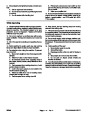
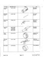
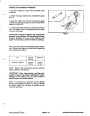
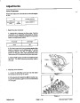
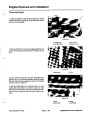
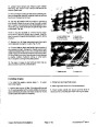
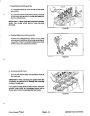
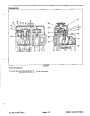
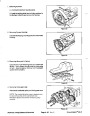
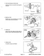
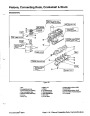
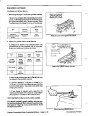
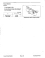
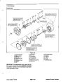
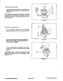
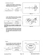
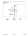
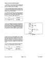
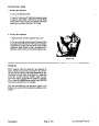
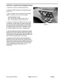
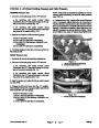
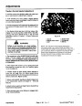
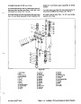
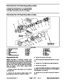
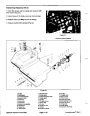
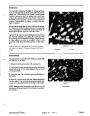
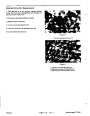
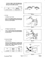
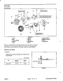
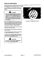
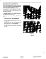
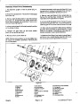
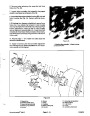
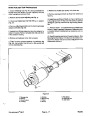
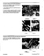
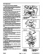
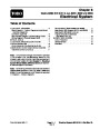
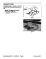
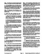
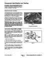
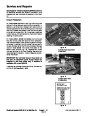
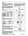
Inspect drive shaft gear and idler gear (Fig. 39C):
SCRIBE MARK
A. Drive shaft spline should be free of twisted or bro-
ken teeth.
B. Gear shafts should be free of rough surfaces and
excessive wear at bushing points and sealing areas.
Scoring, rough surfaces or wear on gear shafts indi-
cates need for replacement.
C. Gear teeth should be free of excessive scoring
and wear. Any broken or nicked gear teeth must be
replaced.
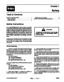
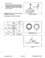
Figure 39B
D. Inspect gear face edge for sharpness. Sharp
edges of gears will mill into wear plates and, thus,
must be replaced.
3
2
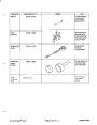
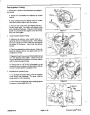
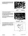
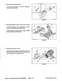
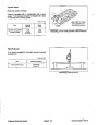
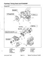
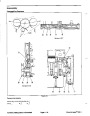
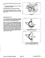
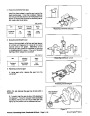
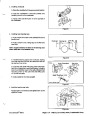
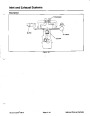
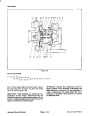
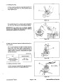
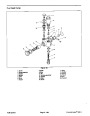
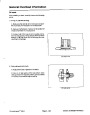
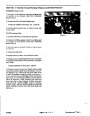
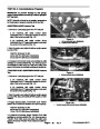
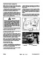
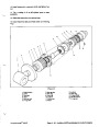
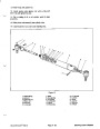
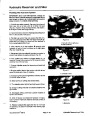
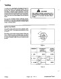
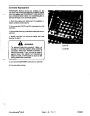
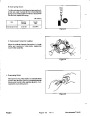
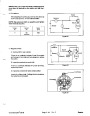
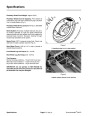
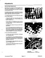
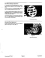
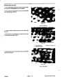
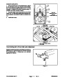
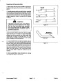
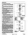
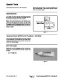
Assembly
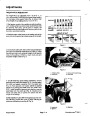
Note:
When assembling the pump, check the marker
or scribe marks on each part to make sure that parts are
properly aligned during assembly (Fig. 39B).
4
1
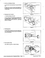
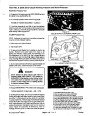
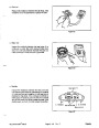
1.
Lubricate new sealing rings, pre--load seal and load
seal with a thin coat of petroleum jelly.Lubricate allother
internal parts freely with clean hydraulic oil.
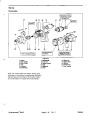
Figure 39C
3.
4.
1.
2.
Gear shaft spline
Gear shaft
Gear teeth
Gear face edge
2.
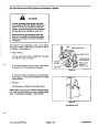
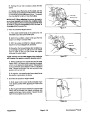
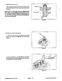
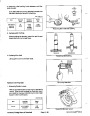
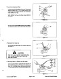
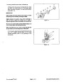
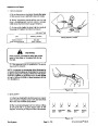
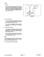
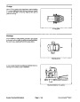
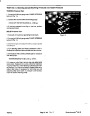
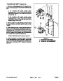
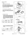
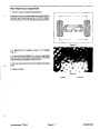
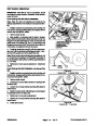
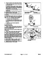
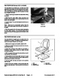
Install new shaft seal in front body. Seal should be
pressed intoplaceuntilitreachesthebottomofthebore.
Grease seal lip.
IMPORTANT: To prevent shaft seal damage during
assembly, use seal protector or tape on drive shaft
splines.
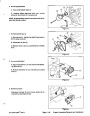
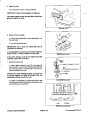
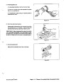
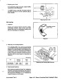
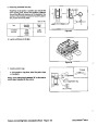
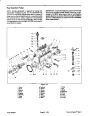
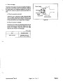
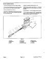
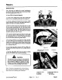
3.
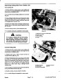
Place rear cover on a flat surface.
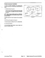
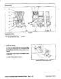
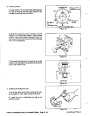
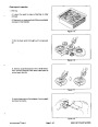
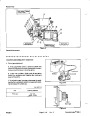
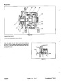
10.Gently
slide the front body onto the assembly. Make
4.
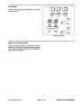
Installthesealingringintotherearcovergroove.Fol-
sure to align scribe marks on the front body and gear
plate.Firmhandpressureshouldbesufficienttoengage
the dowels.
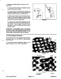
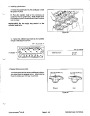
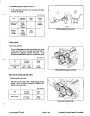
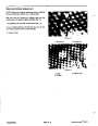
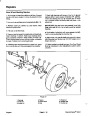
low by placing the rear wear plate on the cover. Make
sure to position the wear plate as shown in Figure 39A
with the bronze side toward the gear position. Lubricate
the exposed side of the rear wear plate with clean hy-
draulic oil.
11.Check to make sure that pump component surfaces
are flush. If gaps exist between components, check as-
sembly for a shifted seal or sealing ring. Correct before
proceeding.
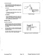
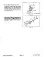
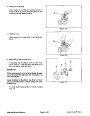
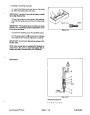
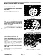
5.
Lubricate the drive shaft and idler gear with clean hy-
draulic oil and install the gears into the proper bearings
in the rear cover. Make sure to align the gears using
mark placed during disassembly.
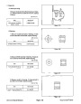
12.Install cap screws and hand tighten to secure as-
sembly.
6.
Install locating dowels in rear cover.
13.Place mounting flange of the pump into a vise and al-
ternately torque the screws from 360 to 380 in--lbs (40.7
to 42.9 N--m).
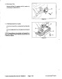
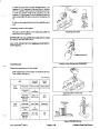
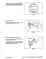
7.
scribe marks on the gear plate and rear cover.
Carefully install gear plate making sure to align
14.Remove
pump from vise.
8.
Lubricate bronze side of front wear plate with clean
hydraulic oil.Place thefrontwearplate onthedriveshaft
and idler gear. Make sure to position the wear plate as
shown in Figure 39A with the bronze side toward the
gears.
15.Place asmallamountofcleanhydraulic oilintheinlet
of the pump and rotate the drive shaft one revolution. If
any binding is noted, disassemble the pump and check
for assembly problems.
9.
Install new pre--load seal, load seal and sealing ring
to the front body.
Auxiliary (Lift/Counterbalance) System Repairs Page 4 -- 44.2
Groundsmaster 580--D
Rev. E
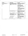
| Categories | Lawn Mower Manual, Sprinkler and Irrigation Manuals, Toro Sprinkler and Irrigation Manuals |
|---|---|
| Tags | Toro Groundsmaster 30581, Toro Groundsmaster 580 D |
| Download File |
|
| Document Type | Service Manual |
| Language | English |
| Product Brand | Toro. Customer Service Representatives are available by phone:
Monday - Friday 7:30 a.m. to 9:00 p.m. (CDT) - Saturday 8:00 a.m. to 8:00 p.m. (CDT) - Sunday 10:00 a.m. to 8:00 p.m. (CDT)
Canada 1-888-225-4886 USA 1-888-384-9939, Lawn Mower |
| Document File Type | |
| Publisher | toro.com |
| Wikipedia's Page | Toro Company |
| Copyright | Attribution Non-commercial |
(0 votes, average: 0 out of 5)