


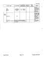
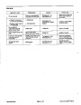

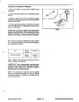
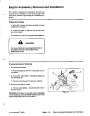


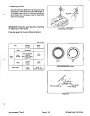


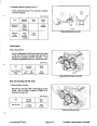


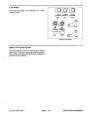


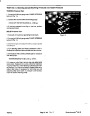


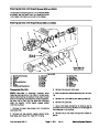
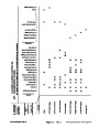


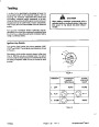


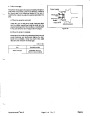
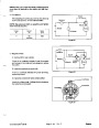
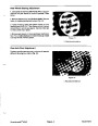


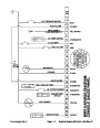
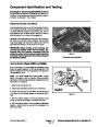


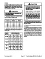


Note:
The red text on the overlay decal refers toinput
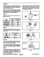
Note:
It may be necessary to toggle between Inputs
switches and the green text refers to output switches.
Displayed and Outputs Displayed several times to do
the following step. To toggle back and forth, press
Toggle Input/Output button once. This may be done as
often as required. Do not hold button.
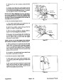
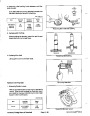
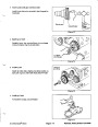
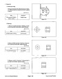
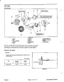
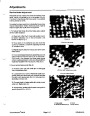
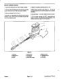
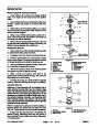
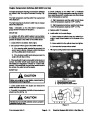
5.
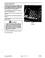
The Inputs Displayed LED on lower right column of
theDiagnosticACEshouldbelighted.IftheOutputsDis-
played LED is lighted, press and release Toggle Input/
Output button on Diagnostic ACE to change to the
Inputs Displayed LED. Do not hold button down.
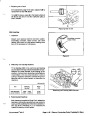
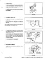
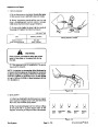
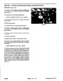
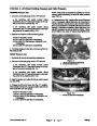
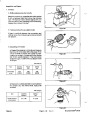
6. Operate desired function switch on the machine.
The appropriate output LED’s should illuminate to indi-
cate that the ECU is turning on that function.
Note:
The Diagnostic ACE will illuminate a LED
associated with each input when its associated input
switch is closed.
Note:
If any output LED is blinking, this indicates an
electrical problem with that OUTPUT. Repair or replace
defectiveelectricalpartsimmediately.Toresetablinking
LED, turn Ignition switch to OFF and then back to ON.
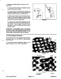
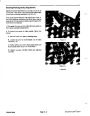
6.
Change each switch individually from open to
closed (i.e., sit on seat, engage traction pedal, etc.).
If output LED’s are not blinking and not lighted, verify
that the required input switches are in their necessary
positions to allow that function to occur. Verify correct
switch position or output.
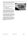
A. Observe that the appropriate LED on Diagnostic
ACE blinks on and off when its corresponding
switch is opened and closed. Check each switch
that can be actuated by hand.
If the output LED’s are on as specified with the machine
not functioning properly, a non--electrical problem exits.
Repair as necessary.
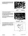
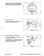
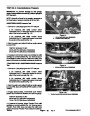
B. Now start engine and raise and lower each cut-
ting unit. Note the appropriate LED on the Diagnos-
tic ACE (i.e. LED is illuminated when cutting unit is
loweredandLEDisnotilluminatedwhencuttingunit
is raised.
If each input switch is in the correct position and func-
tioning correctly with the output LED’s not correctly
lighted, an ECU problem exits. If this condition occurs,
contact your Toro Distributor for assistance.
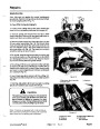
7.
If switch is closed and appropriate LED does not
turn on, check all wiring and connections to switch and/
or check switch with an ohm meter. Replace any defec-
tive switches and repair any defective wiring.
Note:
Due to electrical system constraints, the output
LED’s for “START”, “MONITOR” and “ETR/ALT” may
notblink even though anelectrical problem may existfor
those functions. If the machine problem appears to be
with one of these functions, be certain to check the elec-
trical circuit with a volt / ohm meter to verify that no elec-
trical problem exists to these functions.
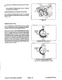
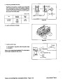
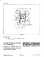
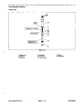
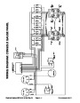
Verify Output Function
The Diagnostic ACE also has the ability to detect which
output solenoids or relays are turned on. This is a quick
way to determine if a machine malfunction is electrical
or hydraulic.
If electronic controller experiences an output failure for
either the cruise control or one of the cutting units, the
controller will disable the machine function.
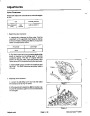
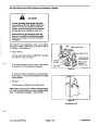
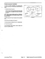
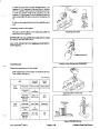
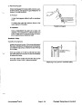
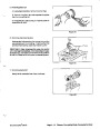
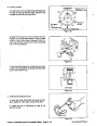
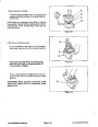
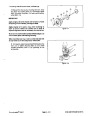
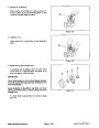
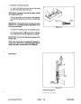
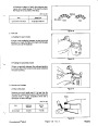
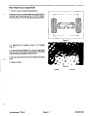
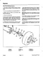
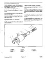
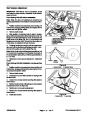
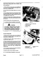
1.
Park machine on a level surface, lower the cutting
units, stop the engine and engage the parking brake.
Indications that this is the cause of the problem include:
A. Flashing green diagnostic light.
B. Diagnostic ACE will illuminate the “output fail”
LED.
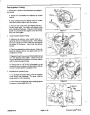
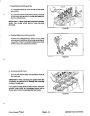
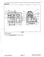
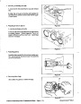
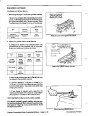
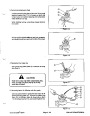
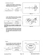
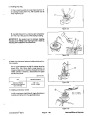
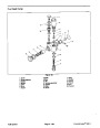
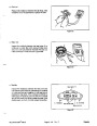
2.
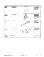
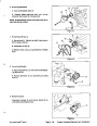
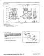
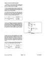
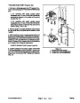
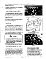
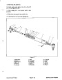
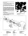
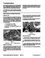
ler. Carefully unplug loopback connector from harness
connector.
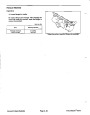
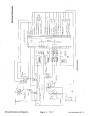
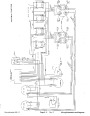
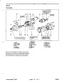
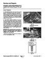
Locate wire harness and connectors near control-
3.
nessconnector.Makesurecorrect overlaydecalisposi-
tioned on Diagnostic ACE.
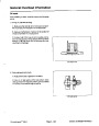
Connect the Diagnostic ACE connector to the har-
C. Diagnostic ACE will flash which output failed.
D. Machine will not respond to ignition key inputs.
Theaboveindicates anECUproblem,contactyourlocal
Authorized TORO Distributor for assistance.
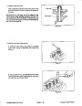
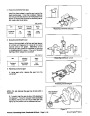
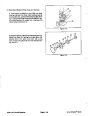
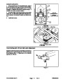
4.
Turn Ignition switch to ON; do not start machine.
If each output switch is in the correct position and func-
tioning correctly, but the output LED’s are not correctly
illuminated, this indicates an ECU problem. If this oc-
curs, contact your Toro Distributor for assistance.
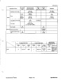
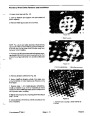
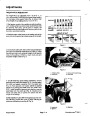
Note:
switches and the green text refers to output switches.
The red text on the overlay decal refers toinput
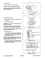
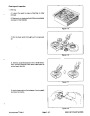
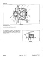
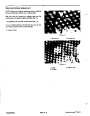
5.
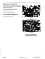
The Outputs Displayed LED on the lower right col-
umn of the Diagnostic ACE should be lighted. If the In-
puts
Displayed
LED
is
lighted,
press
Toggle
Input/Output button on the Diagnostic ACE to change
the LED to Outputs Displayed.
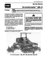
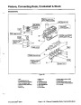
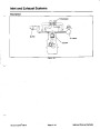
Groundsmaster 580--D
Page 8 -- 9
Electrical System (S/N 30101 & Up) (Rev. E)
| Categories | Lawn Mower Manual, Sprinkler and Irrigation Manuals, Toro Sprinkler and Irrigation Manuals |
|---|---|
| Tags | Toro Groundsmaster 30581, Toro Groundsmaster 580 D |
| Download File |
|
| Document Type | Service Manual |
| Language | English |
| Product Brand | Toro. Customer Service Representatives are available by phone:
Monday - Friday 7:30 a.m. to 9:00 p.m. (CDT) - Saturday 8:00 a.m. to 8:00 p.m. (CDT) - Sunday 10:00 a.m. to 8:00 p.m. (CDT)
Canada 1-888-225-4886 USA 1-888-384-9939, Lawn Mower |
| Document File Type | |
| Publisher | toro.com |
| Wikipedia's Page | Toro Company |
| Copyright | Attribution Non-commercial |
(0 votes, average: 0 out of 5)