


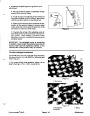
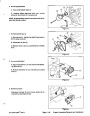


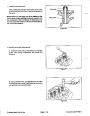
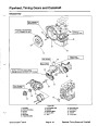


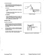
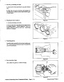


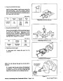
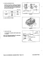
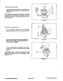
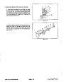


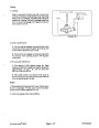
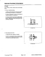


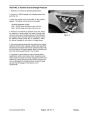
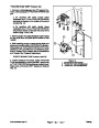


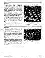


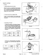
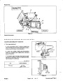
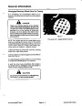
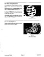


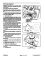


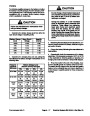


2.
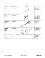
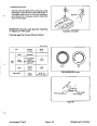
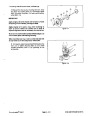
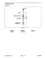
Using an arbor press, push outer bearing spacer
into top ofspindle housing; tightly against snap ring.The
spacer must contact the snap ring to be sure of the
correct assembly of components.
PRESS
4
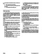
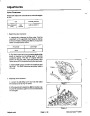
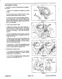
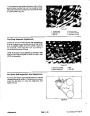
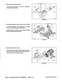
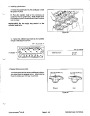
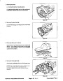
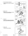
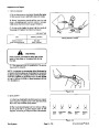
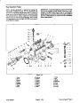
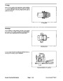
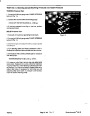
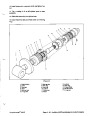
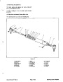
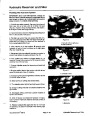
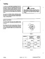
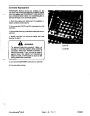
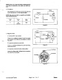
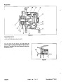
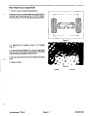
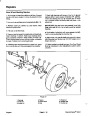
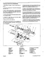
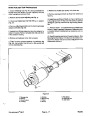
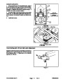
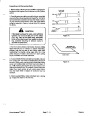
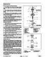
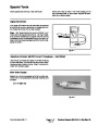
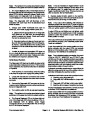
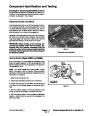
3.
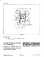
Thoroughly oil the bearing cups. Use an arbor press
to push the bearing cups into the top and bottom of the
spindle housing. The top bearing cup must contact the
spacer that was installed in step 2, and the bottom
bearing cup must contact the snap ring. Make sure that
the assembly is correct by supporting the first cup and
pressing the second cup against it (Fig. 27).
3
1
2
6
5
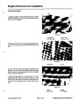
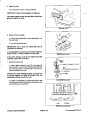
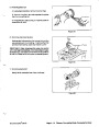
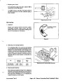
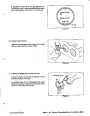
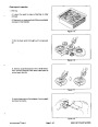
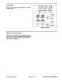
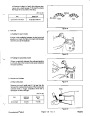
4.
Apply a film of grease on lips of both seals. Pack the
bearing cones with grease.
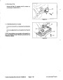
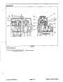
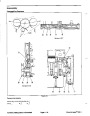
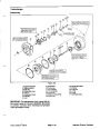
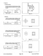
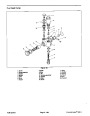
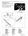
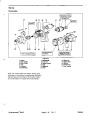
Figure 27
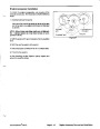
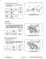
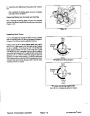
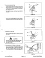
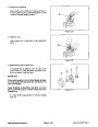
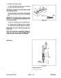
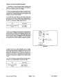
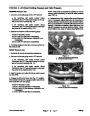
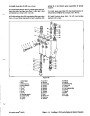
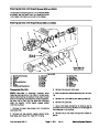
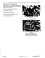
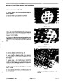
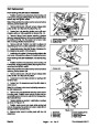
5.
Install bearing cone and seal into bottom of spindle
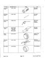
1.
2.
3.
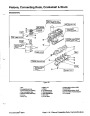
Bearing Cup
Large Snap Ring
Large Spacer
4. Arbor Press
5. Support
6. Arbor Press Base
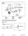
housing. BOTTOM SEAL MUST HAVE THE LIP
FACING OUT so old grease can be purged during
spindle lubrication.
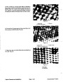
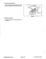
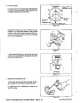
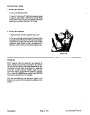
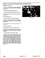
7.
Slide spacer ring and inner bearing spacer into
spindle housing. Install bearing cone and seal into top of
spindle housing. UPPER SEAL MUST HAVE THE LIP
FACING IN.
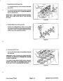
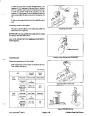
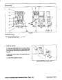
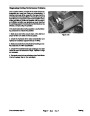
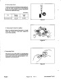
6.
Check the spindle shaft to make sure it is free of
burrs and nicks that could possibly cut the seals. Thor-
oughly lubricate the shaft and seal lips.
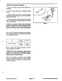
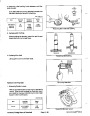
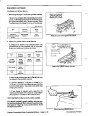
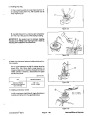
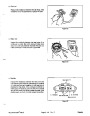
8.
Slide spindle shaft spacer onto spindle shaft.
Carefully slide spindle shaft through spindle housing.
The bottom seal and spindle shaft spacer should fit
together when the spindle is fully installed.
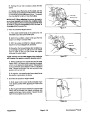
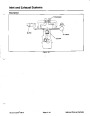
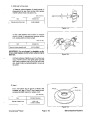
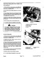
9.
If equipped, position o--ring to top of spindle shaft.
Push pulley onto splines of spindle shaft and secure
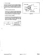
10.
spindle assembly with thrust washer and lock nut.
Tighten the lock nut from 140 to 160 ft--lb (190 to 217
N--m). Rotate the spindle shaft to be sure that the shaft
rotates freely.
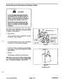
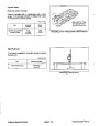
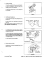
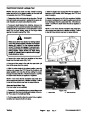
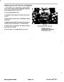
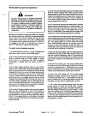
11.
Attach a hand grease gun to grease fitting and fill
cavity with grease until grease starts to come out of low-
er seal. NOTE: Pneumatic grease guns can cause air
pockets when filling large cavities with grease and
therefore, are not recommended to be used for proper
greasing of spindle housings.
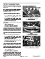
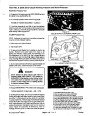
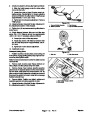
Installing Spindle Housing Assembly
1.
Position spindle assembly to cutting unit. Secure
the spindle assembly in place with six (6) carriage bolts
and flange nuts.
2.
Install the belt (see Belt Replacement in this sec-
tion). Check and adjust belt tension (see Inspecting and
Adjusting Cutting Unit Belt Tension in the Adjustments
section).
3.
Reinstall the belt covers.
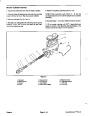
4.
Position blade (blade sail facing up) and anti--scalp
cup to spindle shaft. Secure with lock washer and blade
bolt. Torque bolt from 140 to 165 ft--lb (190 to 217 N--m).
Repairs
Groundsmaster 580--D
Page 7 -- 16 Rev. E
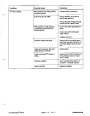
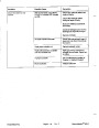
| Categories | Lawn Mower Manual, Sprinkler and Irrigation Manuals, Toro Sprinkler and Irrigation Manuals |
|---|---|
| Tags | Toro Groundsmaster 30581, Toro Groundsmaster 580 D |
| Download File |
|
| Document Type | Service Manual |
| Language | English |
| Product Brand | Toro. Customer Service Representatives are available by phone:
Monday - Friday 7:30 a.m. to 9:00 p.m. (CDT) - Saturday 8:00 a.m. to 8:00 p.m. (CDT) - Sunday 10:00 a.m. to 8:00 p.m. (CDT)
Canada 1-888-225-4886 USA 1-888-384-9939, Lawn Mower |
| Document File Type | |
| Publisher | toro.com |
| Wikipedia's Page | Toro Company |
| Copyright | Attribution Non-commercial |
(0 votes, average: 0 out of 5)