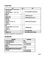


Description
Light Kit (standard on 38559)
Differential Kit
Part Number
66-7941 (model 38546)
38038
Assembly
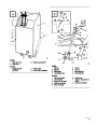
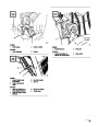
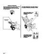
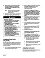
Install Shift Rod (Fig. 5)
1.
Insert upper shift rod ball joint stud through
front of shift bracket and secure with 3/8-16
locknut.
Note:
Determine left and right sides of
snowthrower by standing in the normal
operating position.
Note:
Shift rod to be positioned with bend
rearward.
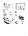
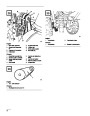
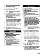
Mount Auger/impeller Housing
2.
3.
Insert bottom ball joint stud through right side of
transmission lever and secure with 3/8-16
locknut.
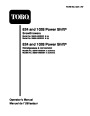
1.
Remove (2) flange head capscrews securing idler
pulley assembly to engine frame. Remove idler
pulley assembly.
Shift into 2nd gear and check shift rod alignment
with Power Shift slot.
2.
Align auger/impeller housing and engine frame
mounting holes (Fig. 2).
Note:
If gear shift lever is not aligned with
Power Shift slot in control panel
(Fig. 5, inset), shift rod length must be
adjusted as follows:
3.
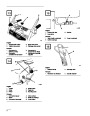
4.
Route impeller belt around impeller pulley.
Secure auger/impeller housing to engine frame
with (6) 5/16-18x3/4” lg. flange head capscrews.
A.
B.
C.
Disconnect ball joint from transmission
lever and loosen jam nut.
5.
Reinstall idler pulley assembly. Make sure idler
pulleys are aligned with belts when reinstalling
idler pulley assembly.
Rotate ball joint up or down, until gear shift
lever is aligned with Power Shift slot.
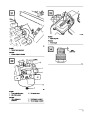
6.
7.
Tip snowthrower up on front edge of
auger/impeller housing.
Reinstall ball joint to transmission lever and
tighten jam nut.
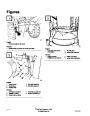
Mount lower belt cover to underside of
auger/impeller housing and engine frame with
(2)
3).
1/4-20x1/2” lg. flange head capscrews (Fig.
Make sure belt cover mounting tabs are
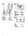
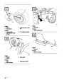
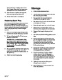
Install Discharge Chute (Fig. 6)
positioned to rear of engine frame member.
Note:
Before installing discharge chute,
apply a light coat of low temperature
grease to chute ring.
8.
Check adjustment of impeller cable; refer to step
3
of Adjusting Auger/Impeller Drive Belt,
page 19.
1.
Set discharge chute—open side forward—onto
auger discharge opening, so plastic chute
retainers are positioned on chute ring. Make sure
chute retainer guide pins are inserted into holes
in chute gear.
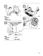
9.
Mount upper belt cover to engine frame with (3)
1/4-20x1/2”
lg. flange head capscrews (Fig. 4).
10.
Slide cable cover onto cables and into hole in
belt cover (Fig. 4).
GB–11
| Categories | Snow Blower Manuals, Toro Snow Blower |
|---|---|
| Tags | Toro 1028 Power Shift, Toro 38558, Toro 38559 |
| Model Number | 38559 |
| Model Year | 1999 |
| Download File |
|
| Document Type | Operator's Manual |
| Language | Français |
| Serial Number | 99000001 - 99999999 |
| Product Name | Toro 1028 Power Shift Snowthrower |
| Product Brand | Toro. Customer Service Representatives are available by phone:
Monday - Friday 7:30 a.m. to 9:00 p.m. (CDT) - Saturday 8:00 a.m. to 8:00 p.m. (CDT) - Sunday 10:00 a.m. to 8:00 p.m. (CDT)
Canada 1-888-225-4886 USA 1-888-384-9939, Snow Blower |
| Product Type | Snowthrower |
| Product Series | Snowthrower, Two Stage Power Shift |
| Swath | 21 inch |
| Discharge | Two Stage |
| Engine Manufacturer | Tecumseh |
| Engine Oil Type | 26 oz. (.8l) 5w-30 or 10w / API SH or higher |
| Gearbox Lubricant | 4.5 oz. (133ml) SAE 90 GL5 or higher |
| Engine Motor Model # | OHSK100-221607A |
| Engine Motor Size | 10 hp |
| Engine Motor Type | 4 Cycle CARB1, EPA1 |
| Transmission Speed | 4 Forward/2 Reverse |
| Transmission Type | Gear |
| Document File Type | |
| Publisher | toro.com |
| Wikipedia's Page | Toro Company |
| Copyright | Attribution Non-commercial |
(0 votes, average: 0 out of 5)