


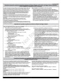

MAINTENANCE
CHECK AND ADJUST THE CABLES
The cables are adjusted at the factory and no adjustment should be neces-
sary. If the cables have become stretched or are sagging adjustment will
be necessary.
6. Release the auger control lever. The auger must stop within 5 sec-
onds.
7. If the auger does not operate properly, stop the engine and recheck
the auger control cable adjustment.
Whenever belts are adjusted or replaced, the cables will need to be ad-
justed.
8. If the drive linkage is properly adjusted, the tension of the auger drive
belt may require an adjustment (see “Belt Adjustment” section).
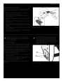
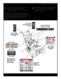
Auger Control Cable Adjustment
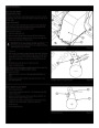
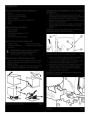
Traction Control Cable Adjustment
1.
Remove the gas from the gas tank. Stand the snowthrower up on the
front end of the auger housing.
WARNING: Do not over-tighten, as this may lift the
lever and cause the auger drive to be engaged with-
out depressing the auger control lever.
WARNING: Drain the gasoline outdoors, away from fire
or flame.
WARNING: Drain the gasoline outdoors, away from
fire or flame.
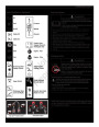
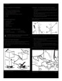
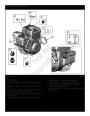
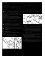
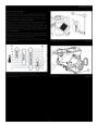
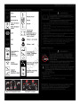
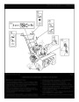
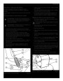
2. Loosen the bolts (A, Figure 33) on each side of the bottom panel (B).
3.
4.
Remove the bottom panel.
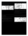
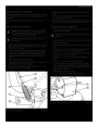
Slide the cable boot (A, Figure 34) off the cable adjustment bracket
(B).
Push the bottom of the traction drive cable (C) through the cable
adjustment bracket until the “Z” hook (D) can be removed.
Remove the “Z” hook from the cable adjustment bracket. Move the “Z”
hook down to the next adjustment hole.
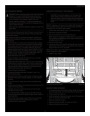
1.
2.
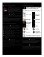
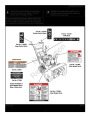
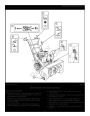
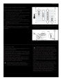
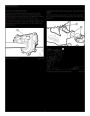
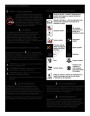
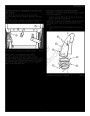
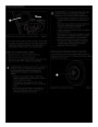
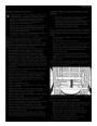
With the auger control lever released, the hook (A, Figure 32) should
barely touch the lever (B) without raising it. There can be a maximum
of 1/32" (0.8 mm) clearance.
To adjust, loosen the nut (C) by holding the adjusting flats (D) and
turning the nut. Then, turn the adjusting flats and hold the adjust-
ment screw (E). The adjustment screw is a phillips screw and the
head can be held or turned by inserting a screwdriver through the
spring (F).
Hold the adjusting flats and tighten the nut.
Start the engine and check the auger. The auger must not be engaged
unless the auger control lever is depressed.
5.
6.
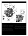
7. Pull the traction control cable up through the cable adjustment
bracket.
8.
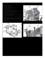
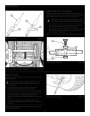
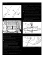
9. To check the adjustment, depress the control lever and check the
length of the drive spring (A, Figure 35). In correct adjustment, the
length of the drive spring is a minimum 3 inches (76 mm) and a max-
imum 3-3/8 inches (85 mm).
3.
4.
Put the cable boot over the cable adjustment bracket.
5.
With the engine running, fully depress the auger control lever. The
auger should engage and run normally.
10.
Install the bottom panel (B, Figure 33).
11.
Tighten the bolts (A) on each side of the bottom panel.
D
C
A
B
F
E
A
1/32”
(0.8mm)
B
Adjusting Traction Control Cable
Figure 33
Adjusting Auger Control Cable
Figure 32
27
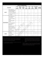
| Categories | Murray Snow Blower Manuals, Snow Blower Manuals |
|---|---|
| Tags | Murray 1695719 |
| Download File |
|
| Document File Type | |
| Copyright | Attribution Non-commercial |
(0 votes, average: 0 out of 5)