


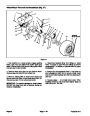


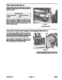
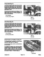
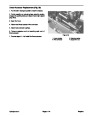

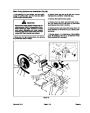


14.
from housing.
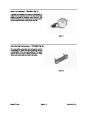
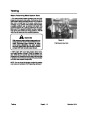
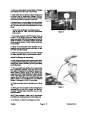
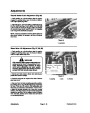
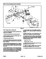
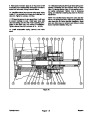
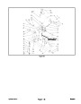
Remove pump shaft (Item 19) and bearing assembly
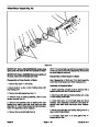
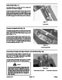
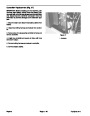
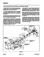
3. Install displacement control shaft (Item 12) into hous-
ing.
15.
washer, if used). Press shaft out of bearing.
Remove outer bearing retaining ring (Item 21) (and
4. If block spring retaining ring (Item 10) was removed
from pump shaft, install a new retaining ring at this time.
16.
(Item 10) requires replacement, remove it from pump
shaft.
If pump block retaining spring retaining ring
5. Install inner bearing retaining ring (Item 20) onto
shaft. Press bearing (Item 21) onto shaft, install washer
(if used) and new outer bearing retaining ring. Be careful
not to stretch or deform retaining rings.
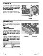
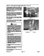
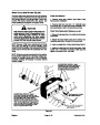
17.
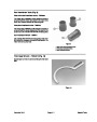
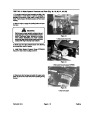
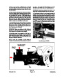
Remove displacement control shaft from housing.
IMPORTANT: Be careful not to damage shaft sealing
surface.
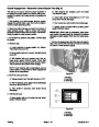
18.
Pry displacement control shaft seal out of housing.
Care must be taken so as not to damage housing bore.
If displacement control shaft journal bearing re
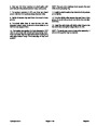
6.
Install pump shaft and bearing assembly intohousing.
19.
quires replacement, press it out of housing.
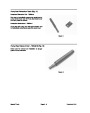
7. Install bearing spacer washer (Item 22).
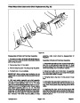
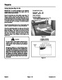
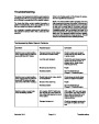
Inspection and Replacement of Pump Parts
8. Wrap shaft with thin plastic or use a seal protector to
prevent damage to seal during installation. Lubricate
new pump shaft seal (Item 23) with petroleum jelly.
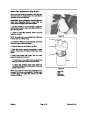
After disassembly, thoroughly clean all parts in a suit
able solvent. Replace all o-rings, gaskets and seals.
9.
Slide seal over shaft and press it into housing bore.
Inspect all parts for damage, nicks or unusual wear
patterns. Replace all parts having unusual or excessive
wear or discoloration.
Be careful not to damage the seal.
10. Install retaining ring (Item 24).
Inspect seal surfaces, bearing surfaces and shaft spli
nes. Polish sealing areas on shafts if necessary. Re
place any worn or damaged parts.
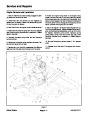
11. Install swashplate cradle bearings (Item 14) into
housing, making sure they are located on cast-in pins
in housing.
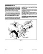
The pump shaft bushing (Item 5) is pressed into end cap
and is usually not removed.
12. Install slot guide block (Item 13) onto displacement
control shaft.
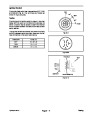
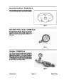
The running surfaces of cylinder blocks MUST be flat
and free from scratches. If scratches or wear are found
on running surfaces of cylinder blocks or end cap, polish
or replace the parts. When polishing these surfaces, up
to 0.0004 in. may be removed. If this is not sufficient to
obtain a flat surface, free of scratches, the part should
be replaced.
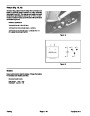
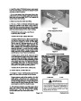
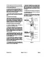
13. Install thrust plate (Item 11) into swashplate
(Item 25). Slot on swashplate must engage guide block
(Item 13) on displacement control shaft (Item 12). Use
a tool such as a screwdriver or magnet to hold guide
block in position while installing swashplate.
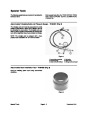
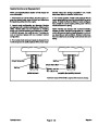
14. Hold swashplate in position and use a dial indicator
or depth gauge to measure side play of displacement
control shaft. Using a suitable sleeve, press control
shaft bearing into housing until control shaft end play is
between 0.020 and 0.060 in.
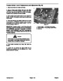
Assembly of Hydraulic Pump
1.
Clean and lightly oil parts before assembly. Tighten
all threaded parts to recommended torque value.
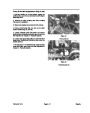
15.
Install thrust washer (Item 9) and cylinder block
IMPORTANT: Most parts have critical, high toler�
ance surfaces. Use caution to prevent damage to
these surfaces during assembly. Protect exposed
surfaces, openings and ports from damage and
foreign material.
spring (Item 8) onto pump shaft.
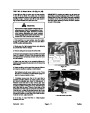
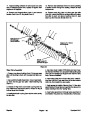
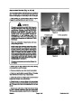
16. Install springs (Item 29), piston washers (Item 28)
and pistons (Item 27) into cylinder block kits. The pis
tons must move freely in their bores.
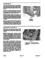
2.
If displacement control shaft bearing (Item 17) has
17. With pump swashplate in “neutral” (0 angle) position
and pump housing laying on its side, install pump cylin
der block kit onto pump shaft in housing.
been removed, press a new bearing into housing using
a suitable press pin. Surface of bearing should be flush
with inside surface of housing.
NOTE: The position of the bearing in the housing deter
mines control shaft end play. Do not press bearing
deeper into housing at this time.
Repairs
Page 4 - 20
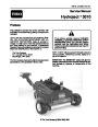
Hydroject 3010
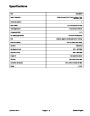
| Categories | Lawn Mower Manual, Sprinkler and Irrigation Manuals, Toro Sprinkler and Irrigation Manuals |
|---|---|
| Tags | Toro Hydroject 3010 |
| Download File |
|
| Document Type | Service Manual |
| Language | English |
| Product Brand | Toro. Customer Service Representatives are available by phone:
Monday - Friday 7:30 a.m. to 9:00 p.m. (CDT) - Saturday 8:00 a.m. to 8:00 p.m. (CDT) - Sunday 10:00 a.m. to 8:00 p.m. (CDT)
Canada 1-888-225-4886 USA 1-888-384-9939, Lawn Mower |
| Document File Type | |
| Publisher | toro.com |
| Wikipedia's Page | Toro Company |
| Copyright | Attribution Non-commercial |
(0 votes, average: 0 out of 5)