


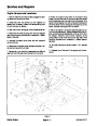


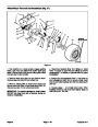

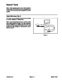

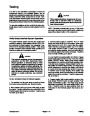
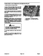

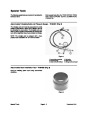
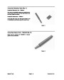
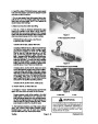
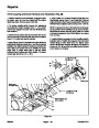
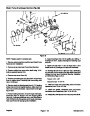

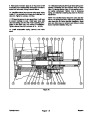
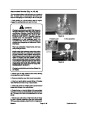
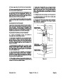


Controller (Fig. 11)
The controller senses the condition of various switches,
such as the transport switch and aerate start switch and
directs power output to allow certain machine functions,
such as aerate engage, disengage and timing of those
functions.
Because of the solid state circuitry built into the control
ler, there is no method to test it directly. The controller
may be damaged if an attempt is made to test it with an
electrical test device, such as a volt-ohm meter.
1
2
3
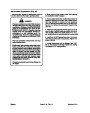
IMPORTANT: Before welding on the machine, dis�
connect both battery cables from the battery, dis�
connect both wire harness plugs fromtheelectronic
control unit and disconnect the terminal connector
from the alternator to prevent damage to the electri�
cal system.
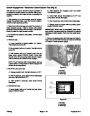
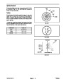
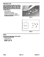
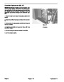
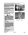
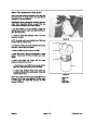
Figure 11
1. Red light
2. Yellow light
3. Green light
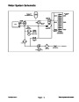
Lights (LED’s) on the controller indicate the condition of
the interlock switches. The LED’s, in conjunction with
the following tests for interlock switches, should be used
to help isolate a problem in an interlock switch, wiring
or the controller (see Wiring Schematics and Diagrams).
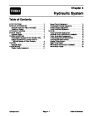
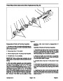
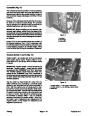
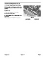
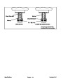
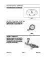
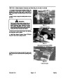
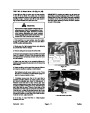
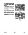
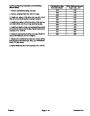
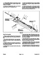
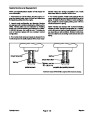
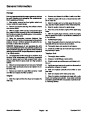
Traction Switch 1 and 2 (Fig. 12)
Traction switch 1 is normally open (N.O.) and is closed
when traction bail is neutral. Traction switch 2 is nor
mally closed (N.C.) and is open when the traction bail is
in neutral.
3
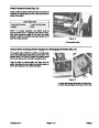
IMPORTANT: Traction switch 1 and 2 have three (3)
terminals. Traction switch 1 must have the wires
connected to the “COMMON” and “N.O.” terminals.
The Traction switch 2 must have the wires con�
nected to the “COMMON” and “N.C.” terminals. If
the wires are not connected to the correct terminals,
on each switch the safety interlock circuit will not
function properly.
1
2
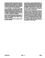
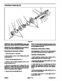
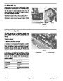
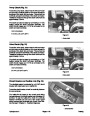
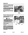
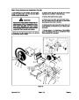
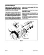
Test the switch by disconnecting the wires from the
switch terminals and connecting a continuity tester
across the two terminals that had wires connected to
them. With the engine turned off, slowly push the trac
tion bail in a forward and reverse direction while watch
ing the continuity tester. There should be indicationsthat
the switch is opening and closing. Allow the traction bail
to return to neutral. There should be continuity across
the terminals of traction switch 1 and no continuity
across the terminals of the traction switch 2. (See Trac
tion Switch 1 and 2 Replacement and Adjustment in the
Repairs section of this chapter for replacement and
adjustment procedures.)
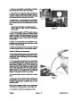
Figure 12
1. Traction switch 1 –– N.O. (gray & black wires)
2. Traction switch 2 –– N.C. (orange & yellow wires)
3. Switch tab
Testing
Page 5 - 18
Hydroject 3010
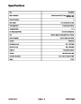
| Categories | Lawn Mower Manual, Sprinkler and Irrigation Manuals, Toro Sprinkler and Irrigation Manuals |
|---|---|
| Tags | Toro Hydroject 3010 |
| Download File |
|
| Document Type | Service Manual |
| Language | English |
| Product Brand | Toro. Customer Service Representatives are available by phone:
Monday - Friday 7:30 a.m. to 9:00 p.m. (CDT) - Saturday 8:00 a.m. to 8:00 p.m. (CDT) - Sunday 10:00 a.m. to 8:00 p.m. (CDT)
Canada 1-888-225-4886 USA 1-888-384-9939, Lawn Mower |
| Document File Type | |
| Publisher | toro.com |
| Wikipedia's Page | Toro Company |
| Copyright | Attribution Non-commercial |
(0 votes, average: 0 out of 5)