


ENGINE REMOVAL AND INSTALLATION
Alternate Method
20” CCR, ALL MODELS, ENGINE
REMOVAL
1.
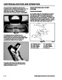
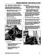
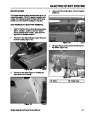
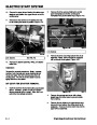
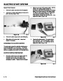
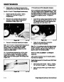
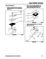
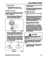
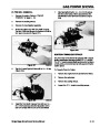
Remove the fuel with a pump type siphon. Tilt the
machine forward so it rests on the rotor housing
and the chute.
The engine can be removed from the top or bottom.
We will cover the steps for both.
2.
3.
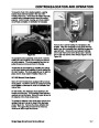
Remove the belt cover, belt, and engine pulley.
1.
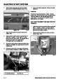
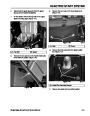
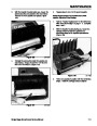
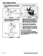
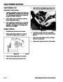
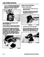
Remove the 3 bolts on the chute and 2 more
where the chute crank attaches to the handle (on
models so equipped). Some models use a chute
handle to rotate the chute; this will come off when
the chute is removed.
Remove the two screws holding the control panel
and let the control panel hang from the starter
rope.
4.
5.
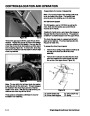
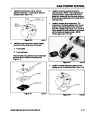
Remove the two hex head capscrews holding the
lower shroud to the handles.
2.
3.
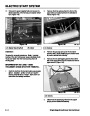
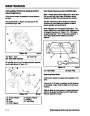
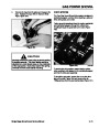
Drain the fuel tank using a pump type siphon.
Remove the 3 screws securing the control panel.
Let the panel hang from the starter rope.
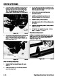
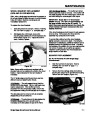
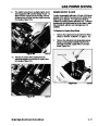
As you lift the lower shroud up, you will need to
reach in and unhook the primer line and the wiring
to the switch. Pull the starter rope out and tie it to
the handle so it doesn’t restrict the removal of the
lower shroud. Caution: The choke lever goes
through a slot in the lower shroud. Do not
4.
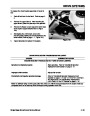
The upper shroud is retained with a bolt and
locknut in each front corner and some have a
screw in each rear corner. On some models, the
rear of the shroud is retained by the control panel.
damage the lever while removing the shroud.
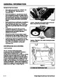
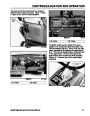
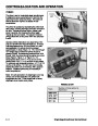
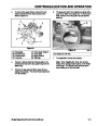
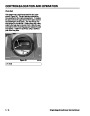
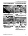
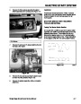
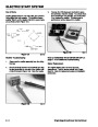
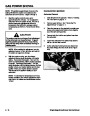
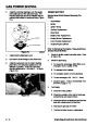
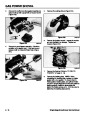
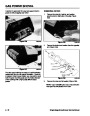
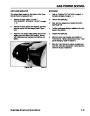
Electric Start models only - The electric start
switch box is attached to the upper shroud or the
control panel (Figure 52). There are 3 screws
next to the electric start button that must be
removed or the wire harness between the switch
box and starter motor will prevent removal of the
shroud (on some models) and engine removal on
all models. Remove the gas cap and the shroud
will lift off.
6.
The balance of engine removal is the same as the
previous process.
POWERLITE, ENGINE INSTALLATION
Installation is the reverse of removal. There are some
things worthy of mentioning.
1.
One engine side plate must be installed over the
engine mounting studs before the engine is placed
in the chassis.
2.
3.
4.
When installing the engine, be sure to feed the
choke lever through the slot in the lower shroud.
After the engine is located in the chassis, install
the second engine plate and the 4 mounting nuts.
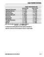
Install the stabilizer bracket to the recoil side of the
engine and torque the nut to 30 in·lbs. Tighten the
4 engine mounting nuts to 170 - 220 in·lbs.
A
Figure 52
1854-11
(A) 3 Screws
Single Stage Snowthrower Service Manual
4 - 7
| Categories | Snow Blower Manuals, Toro Snow Blower |
|---|---|
| Tags | Toro 1028 Power Shift, Toro 1332 Power Shift, Toro 38014, Toro 38030, Toro 38079, Toro 38087, Toro 38400, Toro 38405, Toro 38513, Toro 38543, Toro 38558, Toro 38559, Toro 38574, Toro 624, Toro 824, Toro 828, Toro 924, Toro CCR 1000 |
| Model Year | 1978, 1992, 1993, 1994, 1995, 1996, 1997, 1998, 1999, 2000, 2001, 2002, 2003 |
| Download File |
|
| Document Type | Service Manual |
| Language | English |
| Serial Number | 200000001 - 200999999 |
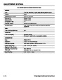
| Product Name | Toro CCR 1000 Snowthrower |
| Product Brand | Toro. Customer Service Representatives are available by phone:
Monday - Friday 7:30 a.m. to 9:00 p.m. (CDT) - Saturday 8:00 a.m. to 8:00 p.m. (CDT) - Sunday 10:00 a.m. to 8:00 p.m. (CDT)
Canada 1-888-225-4886 USA 1-888-384-9939, Snow Blower |
| Product Type | Snowthrower |
| Product Series | CCR 1000/2400/2500, Single Stage, Snowthrower |
| Swath | 20 inch |
| Discharge | Single Stage |
| Engine Manufacturer | Tecumseh |
| Engine Oil Type | Toro 2 cycle / NMMA-TCW3 |
| Engine Motor Model # | HSK635-1721A |
| Engine Motor Size | 3.5 hp |
| Engine Motor Type | 2 Cycle EPA1 |
| Document File Type | |
| Publisher | toro.com |
| Wikipedia's Page | Toro Company |
| Copyright | Attribution Non-commercial |
(0 votes, average: 0 out of 5)