


DRIVE SYSTEMS
Bail Controlled Rotor Engagement System (1999
And Newer Powerlites And All 20” CCR Models
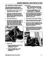
Rotor Cable Adjustment
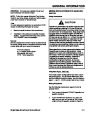
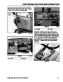
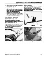
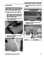
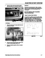
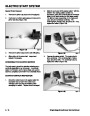
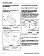
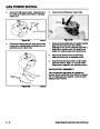
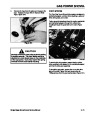
The objective for proper adjustment is that the cable
should be as tight as possible, yet allowing enough
slack that the belt fully disengages and the brake is
applied when the handle is released (Figure 87).
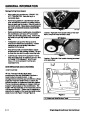
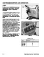
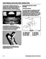
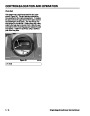
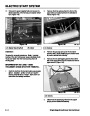
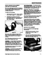
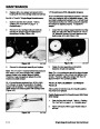
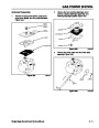
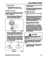
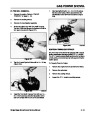
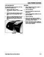
The basic parts of this system are identical to the
spring loaded idler system. The difference is that the
idler arm has been replaced with a combination idler
and brake arm (Figure 86). The idler/ brake arm is
controlled by a cable from a bail on the upper handle.
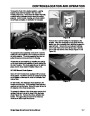
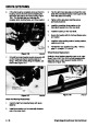
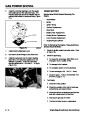
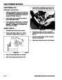
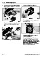
With the belt cover removed the idler/brake arm is
visible. There is a spring connected to the idler/brake
arm. However, in this application the spring applies
pressure to disengage the belt and engage the rotor
brake. When the operator squeezes the bail, the idler
is pulled down, tightening the belt and disengaging the
brake. Because this system has the belt both tight and
loose, a belt guide is necessary to prevent the belt from
falling off the engine pulley when disengaged. The
arms on the belt guide should be about 1/8” from the
back side of the belt, when the belt is engaged.
A
B
C
D
E
A
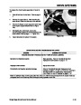
Figure 87
0309-08
J
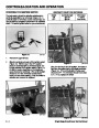
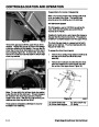
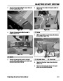
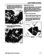
(A) Bail
(B) Spring Cover
(C) Spring
(D) Cable Adjuster
(E) Cable
I
B
C
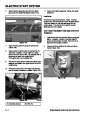
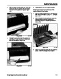
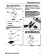
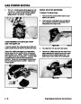
The bail on the upper handle has two holes. The
standard position is in the hole closest to the pivot.
(The outer position is intended for temporary use. If
the belt starts to slip while blowing snow, the cable can
be easily moved to the outer hole in the bail. This
provides extra travel and belt tension to allow finishing
the job.) Following the cable down, locate the spring
cover and pull it back to expose the end of the cable
and the cable adjuster. With the bail released, select
the hole that allows a minimum slack in the cable. Slip
the spring cover back into position.
H
D
E
G
F
Figure 86
0309-09
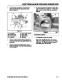
(A) Engine Pulley
(B) Belt Cover
(C) Belt Guide
(D) Idler Pulley
(E) Cable
(F) Rotor
(G) Belt
(H) Hub
(I) Idler/Brake Arm
(J) Brake Spring
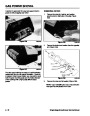
Remember a new belt will wear in during the first use
and readjustment will be necessary.
Single Stage Snowthrower Service Manual
5 - 13
| Categories | Snow Blower Manuals, Toro Snow Blower |
|---|---|
| Tags | Toro 1028 Power Shift, Toro 1332 Power Shift, Toro 38014, Toro 38030, Toro 38079, Toro 38087, Toro 38400, Toro 38405, Toro 38513, Toro 38543, Toro 38558, Toro 38559, Toro 38574, Toro 624, Toro 824, Toro 828, Toro 924, Toro CCR 1000 |
| Model Year | 1978, 1992, 1993, 1994, 1995, 1996, 1997, 1998, 1999, 2000, 2001, 2002, 2003 |
| Download File |
|
| Document Type | Service Manual |
| Language | English |
| Serial Number | 200000001 - 200999999 |
| Product Name | Toro CCR 1000 Snowthrower |
| Product Brand | Toro. Customer Service Representatives are available by phone:
Monday - Friday 7:30 a.m. to 9:00 p.m. (CDT) - Saturday 8:00 a.m. to 8:00 p.m. (CDT) - Sunday 10:00 a.m. to 8:00 p.m. (CDT)
Canada 1-888-225-4886 USA 1-888-384-9939, Snow Blower |
| Product Type | Snowthrower |
| Product Series | CCR 1000/2400/2500, Single Stage, Snowthrower |
| Swath | 20 inch |
| Discharge | Single Stage |
| Engine Manufacturer | Tecumseh |
| Engine Oil Type | Toro 2 cycle / NMMA-TCW3 |
| Engine Motor Model # | HSK635-1721A |
| Engine Motor Size | 3.5 hp |
| Engine Motor Type | 2 Cycle EPA1 |
| Document File Type | |
| Publisher | toro.com |
| Wikipedia's Page | Toro Company |
| Copyright | Attribution Non-commercial |
(0 votes, average: 0 out of 5)